snAPI.Main module#
- class snAPI.Main.snAPI#
Bases:
objectThis is the main class of the snAPI library. When creating the snAPI object the api is initialized. It holds the underlying snAPI.dll (dynamic link library), the
snAPI.deviceConfig, the measurement classes and many other API calls.Note
Creating the snAPI object calls
initAPI(). Please look there for detailed information.- Parameters:
systemIni (str) –
path to the system.ini file (default: “system.ini”)- Return type:
the snAPI object
Example
# This instantiates a snAPI object in sn for TimeHarp260
sn = snAPI()
- is_win = True#
- is_linux = False#
- deviceIDs = []#
This list contains the IDs serial numbers of the connected devices or the file names of the opened file devices (files that act as devices) and will be filled after calling
getDeviceIDs().
- deviceConfig = ()#
The device config contains all information about the initialized device. To update it it is necessary to call
getDeviceConfig().Note
The deviceConfig can not directly be written. It is only for checking the current state. To change the configuration, you have to call the device functions or write the config with
loadIniConfig()orsetIniConfig(). For detailed information read Configuration!Example
# This is an example of a device config

{
"DeviceType": 0,
"FileDevicePath": "",
"ID": "1045483",
"Index": 0,
"Model": "MultiHarp 150 4P",
"PartNo": "930043",
"Version": "1.0",
"BaseResolution": 5.0,
"Resolution": 5.0,
"BinSteps": 24,
"NumChans": 4,
"NumMods": 2,
"SyncDiv": 1,
"SyncTrigMode": "Edge",
"SyncTrigLvl": -50,
"SyncTrigEdge": 1,
"SyncDiscrLvl": -50,
"SyncZeroXLvL": 0,
"SyncChannelOffset": 0,
"SyncChannelEnable": 1,
"SyncDeadTime": 800,
"HystCode": 0,
"StopCount": 4294967295,
"Binning": 1,
"Offset": 0,
"lengthCode": 6,
"NumBins": 65536,
"MeasControl": 0,
"StartEdge": 1,
"StopEdge": 1,
"TrigOutput": 0,
"HoldoffTime": 0,
"HoldTime": 0,
"MarkerEdges": [
    0,
    0,
    0,
    0
],
"MarkerEna": [
    0,
    0,
    0,
    0
],
"ModsCfg": [
    {
    "Index": 0,
    "ModelCode": 1010,
    "VersionCode": 16843029
    },
    {
    "Index": 1,
    "ModelCode": 1000,
    "VersionCode": 17694997
    }
],
"ChansCfg": [
    {
    "Index": 0,
    "TrigLvl": 100,
    "TrigEdge": 1,
    "DiscrLvl": 100,
    "ZeroXLvl": 0,
    "ChanOffs": 0,
    "ChanEna": 1,
    "DeadTime": 800
    },
    {
    "Index": 1,
    "TrigLvl": -120,
    "TrigEdge": 1,
    "DiscrLvl": -120,
    "ZeroXLvl": 1,
    "ChanOffs": 0,
    "ChanEna": 1,
    "DeadTime": 800
    }
],
"MeasMode": 0,
"RefSource": 0
}
- measDescription = ()#
The measurement description contains special information about the measurement. To update it it is necessary to call
getMeasDescription().Note
The measDescription is only valid after a measurement is done or a file device is loaded.
- Parameters
AcqTime: acquisition time
AveSyncRate: if measured with
getCountRates()AveSyncPeriod: if measured with
getSyncPeriod()StopReason: why the measurement was stopped
StopAfter: the determined time after the measurement was stopped
WarningsFlag: currently not supported
NumRecs: total number of records
Example
# This is an example of a measurement description

230908_10:29:08.4519796 EXT {
  "AcqTime": 6000000,
  "AveSyncRate": 0.0,
  "AveSyncPeriod": 4294967295.0,
  "StopReason": "Manual",
  "StopAfter": 252036.0,
  "WarningsFlag": 0,
  "NumRecs": 70791781
}
- correlation#
This is the object to
Correlation. class
- manipulators#
This is the object to
Manipulators. class
- logPrint(*args, **kwargs)#
With logPrint it is possible to print something to the api generated log file. The generated log file entry will be marked with an “EXT” (External).
Note
See
initAPI()for information about the logfile destination and configuration!- Parameters:
args (It should be used like the normal python print function.)
- Return type:
None
Example
# Takes the first available device
sn.logPrint("some text", someVariable)

# This is an example of the log file
230510_11:33:39.4930338 INF ----------------------------------------------
230510_11:33:39.4982656 INF INIT
230510_11:33:39.4983593 INF snAPI 0.1.0.996
230510_11:33:39.4986360 INF API Init
230510_11:33:39.4987400 INF Init MHlib
230510_11:33:39.4988423 DEV MH_GetLibraryVersion: 3.1
- logException(exception, eTraceback)#
This function is for internal use only and captures unhandled exceptions and add them to the log.
Example
# This is an example of the logged exception
230911_12:02:53.5338907 ERR Uncaught python exception: IndexError!
230911_12:02:53.5340906 ERR Text: index 1000000000 is out of bounds for axis 0 with size 300862664
230911_12:02:53.5349062 ERR   File "e:\Projects\source\Harp\PythonWrapper\Tool_ReadPTU.py", line 25, in <module>
230911_12:02:53.5350878 ERR     sn.logPrint(f"{channels[1000000000+i]:9} | {times[i]:8}")
230911_12:02:53.5351972 ERR                    ~~~~~~~~^^^^^^^^^^^^^^
- setLogLevel(logLevel, onOff)#
This function can set or overwrite the logging flags
snAPI.Constants.LogLevelfor logging. These log levels will initially set by the system.ini defined ininitAPI().- Parameters:
logLevel (LogLevel)
onOff (bool)
- Returns:
True (operation successful)
False (operation failed)
Example
# This switches the log entries 'Dev' off

sn.setLogLevel(LogLevel.Device, False)
- initAPI(systemIni='system.ini')#
This function is called by constructor of the snAPI class. It loads a system INI file where it is possible to set flags for logging or change the data path.
- Parameters:
systemIni (str) –
path to the system.ini file (default: “system.ini”)- Returns:
True (operation successful)
False (operation failed)
Example
sn.initAPI("system.ini")

# This is an example of an system INI file

    [Paths]
    # the path where the device configurations are stored
    Config = C:\Data\PicoQuant\Configs

    # the path, where the data (default.ptu) files are stored if no path is specified by `setPTUFilePath`
    # this folder and a subfolder named `log` will automatically generated by `initAPI`
    Data = C:\Data\PicoQuant

    [Log]
    # log to files
    File = 1

    # log to std out
    Console = 1

    # select witch parts should be logged
    [LogLevel]
    Api = 1
    Config = 0
    Device = 1
    DataFile = 0
    Manipulators = 1

    # buffer size in number ofb blocks of 1048576 Bytes
    [Params]
    BufferSize = 128
- exitAPI()#
This is function is called in the snAPI destructor. It deletes the API instance and frees its memory.
- Parameters:
None
- Return type:
None
- getDeviceIDs()#
With this function it is possible to read the device identifiers (serial numbers). This DeviceIDs can be used to identify the devices if more than one are connected. If only on device is connected,
getDevice()can be called directly to get this device.- Parameters:
None
- Returns:
True (operation successful)
False (operation failed)
The list of the device names is stored in deviceNames.They will also be shown in the log.Example
sn.getDeviceIDs()

#Log
230405_12:11:07.8882089 INF API getDeviceIDs ["1045483","","","","","","",""]
- getDevice(*dev)#
The getDevice function acquires a PicoQuant TCSPC device and sets it as the current device. From now on all functions will act on this device until another device is acquired.
- Parameters:
None – takes the first available device
str –
- identifier of device
If the DeviceType is
DeviceType.HWit is the serial numberIf the DeviceType is
DeviceType.Fileit is the file name
int – device index [0..7]
- Returns:
True (A device was acquired)
False (No device was acquired)
Example
# Takes the first available device
sn.getDevice()
sn.getDevice("")
sn.getDevice(0)

# Takes the device with the serial number "1045483"
sn.getDevice("1045483")
- getFileDevice(path)#
This function allows opening a PTU file with a specific path. The file will be handled like a real device. It is possible to read the ptu header with
getDeviceConfig. The measurement classes can then be used to calculate a histogram, a time trace or perform other operations on the data.- Parameters:
path (str) – string of the path to the ptu file
- Returns:
True (The file device was successfully acquired)
False (No file device was acquired)
Example
sn.getFileDevice(r"E:\Data\PicoQuant\CW_Shelved.ptu")
- initDevice(measMode=MeasMode.T2, refSrc=RefSource.Internal)#
This function initializes the device, sets its measurement mode and the reference source. After that it is possible to do measurements on the device.
Note
In case of a file device it is not needed to call initDevice and will be ignored.
- Parameters:
measMode (
snAPI.Constants.MeasMode) – path of the ptu file (default: MeasMode.T2)refSrc (
snAPI.Constants.RefSource) – (default: RefSource.Internal)
- Returns:
True (The device was successfully initialized)
False (Device initialization failed)
Example
sn.initDevice(MeasMode.T3)
- closeDevice(allDevices=True)#
This function closes the current device. If the current device is a file device it closes the file.
- Parameters:
all (bool [True: all opened devices (default) | False: the current device])
allDevices (bool | None)
- Return type:
None
- setMeasurementSubMode(subMode=MeasSubMode.Default)#
The PTU-File-Header contains numerous tags that describe the measurement configuration. These can be used for further analysis. For example, to use the PTU file with SymPhoTime 64 for FLIM analysis, the mandatory parameter Measurement_SubMode must be set to Image.
- Parameters:
subMode (
snAPI.Constants.MeasSubMode)startEdge (int)
- Return type:
None
Example
# set Image Tag
sn.setMeasurementSubMode(subMode=MeasSubMode.Image)
- addBoolTag(name, value, idx=-1)#
This adds a boolean tag to the PTU-Header.
- Parameters:
name (str) – name of the tag
value (bool) – True | False
idx (int | None)
- Return type:
None
Example
# sets the scan pattern
sn.addBoolTag("ImgHdr_BiDirect", False)
- addIntTag(name, value, idx=-1)#
This adds a 64-Bit-Integer tag to the PTU-Header.
- Parameters:
name (str) – name of the tag
value (int)
idx (int | None)
- Return type:
None
Example
# sets the scan pattern
sn.addBoolTag("ImgHdr_BiDirect", False)
- addFloatTag(name, value, idx=-1)#
This adds a Floating-Point-Number tag to the PTU-Header.
- Parameters:
name (str) – name of the tag
value (float)
idx (int | None)
- Return type:
None
Example
#  Sets the Resolution of a single pixel to 0.5µm (line and image measurements)
sn.addFloatTag("ImgHdr_PixResol", 0.5)
- addStringTag(name, value, idx=-1)#
This adds a boolean tag to the PTU-Header.
- Parameters:
name (str) – name of the tag
value (str)
idx (int | None)
- Return type:
None
Example
# sets the name of the objective used on measurement
sn.addStringTag("ImgHdr_ObjectiveName", "20x")
- addByteArrayTag(name, value, idx=-1)#
This adds an Array of Integers tag to the PTU-Header.
- Parameters:
name (str) – name of the tag
value (List[int])
idx (int | None)
- Return type:
None
Example
# sets the scan pattern
sn.addBoolTag("ImgHdr_BiDirect", False)
- addFloatArrayTag(name, value, idx=-1)#
This adds an Array of Floats tag to the PTU-Header.
- Parameters:
name (str) – name of the tag
value (List[float])
idx (int | None)
- Return type:
None
Example
# sets the scan pattern
sn.addBoolTag("ImgHdr_BiDirect", False)
- clearCustomTags()#
This clears all custom Tags, that should be written to the Header of the PTU-File!
- setPTUFilePath(path)#
This function sets the path to the ptu file, if the measurement supports writing the Raw data stream to file. If no special path is set the file will be written to the data path defined in the INI file that was called with
initAPi(). The default file name ist default.ptu.- Parameters:
path (str) – absolute path to the ptu file destination
- Returns:
True (operation successful)
False (operation failed)
Example
sn.setPTUFilePath("C:\Data\PicoQuant\default.ptu")
- loadIniConfig(path)#
The device will be initialized with default parameters from intDevice. If is desired to change a parameter this can be done subsequently with corresponding API call. Alternatively multiple parameters can be conveniently loaded at once by using
loadIniConfig(). This loads an ini configuration file that contains a [Device] section for general device parameters, a [Default] section that will set parameters for all channels and possibly [Channel_N] sections with N starting at 0 for individual channel settings. Only the parameters which need need to be changed have to be defined in the config file.Note
For detailed information read Configuration section! If you encounter any issues reading a config.ini file enable the config log level in the system.ini. The file location is shown in the first log entry: ‘loadSettingsIni: e:pathtosystem.ini’.
- Parameters:
path (str) – path to the device configuration INI file
- Returns:
True (operation successful)
False (operation failed)
Example
sn.loadIniConfig("C:\Data\PicoQuant\Configs\device.ini")

# This is an example for a device INI file
[Device]
HystCode = 0
SyncDiv = 1
SyncEdgeTrig = -50,1
SyncChannelOffset = 0
SyncChannelEnable = 1
SyncDeadTime = 00
StopCount = 4294967295
Binning = 1
Offset = 0
TriggerOutput = 0

[All_Channels]
EdgeTrig = -50,1
ChanOffs = 0
ChanEna = 1
DeadTime = 0

[Channel_0]
EdgeTrig = 0,1
ChanOffs = 0

[Channel_1]
EdgeTrig = -120,1
- setIniConfig(text)#
This command is similar to
loadIniConfig()but it takes the INI string instead of the path to the file.Note
An INI file uses multiple lines to separate the entries. It is therefore necessary to use the separator ‘\n’ to be able to pass it as a single-line string. For detailed information read Configuration! If you encounter any issues setting the config enable the config log level in the system.ini. The file location is shown in the first log entry as follows: ‘loadSettingsIni: e:pathtosystem.ini’.
- Parameters:
text (str) – device configuration INI string
- Returns:
True (operation successful)
False (operation failed)
Example
# sets the Channel 2 Input Edge to -50mV with falling edge
sn.setIniConfig("[Channel_1]\nEdgeTrig = -50,0")
- getDeviceConfig()#
This command reads the device configuration stored by the API and returns it to
snAPI.deviceConfig.Note
Normally you have do not have to call this function in order to refresh the
snAPI.deviceConfig. It should always be up to date automatically. However, under certain circumstances it might be desired to update the device configuration manually. For detailed information read Configuration!- Parameters:
None
- Returns:
True (operation successful)
False (operation failed)
Example
# reads the device config from the API

sn.getDeviceConfig()
- getMeasDescription()#
This reads measurement description that contains special information about the measurement and stores it in
snAPI.measDescription.Note
The measDescription is only valid after a measurement is done or a file device is loaded.
- Parameters:
None
- Returns:
True (operation successful)
False (operation failed)
Example
# reads the measurement description an prints it out

sn.getMeasDescription()
sn.logPrint(json.dumps(sn.measDescription, indent=2))

# prints
230908_11:06:23.9252150 EXT {
  "AcqTime": 6000000,
  "AveSyncRate": 0.0,
  "AveSyncPeriod": 4294967295.0,
  "StopReason": "Manual",
  "StopAfter": 252036.0,
  "WarningsFlag": 0,
  "NumRecs": 70791781
}
- getCountRates()#
This function retrieves the count rates. This measurement is first performed by the hardware by counting with a gate time of 100ms. You will therefore obtain new values only after this time has elapsed. Afterwards the function will return an array of count rates, where the first element is the sync rate, followed by the count rates of the channels.
- Parameters:
None
- Returns:
countrates
- Return type:
array of int
Example
cntRs = sn.getCountRates()
syncrate = cntRs[0]
chan1rate = cntRs[1]
- getSyncPeriod()#
This function only gives meaningful results while a measurement is running and after two sync periods have elapsed. The return value is 0.0 in all other cases. Resolution is the device base resolution. Accuracy is determined by single shot jitter and clock stability.
- Parameters:
None
- Returns:
syncPeriod
- Return type:
float
Example
syncPeriod = sn.getSyncPeriod()
- getNumAllChannels()#
This functions returns the number of available channels from the active device has plus the number of channels for the
Manipulatorsand one for the sync channel. It describes the number of channels a measurement returns and is used for memory allocation.- Parameters:
None
- Returns:
numAllChannels
- Return type:
number of all channels
Example
numChans = sn.getNumAllChannels();
- class snAPI.Main.Device#
Bases:
objectThis is the low level device configuration class. It has to be noted that the functions and parameters you can use depend on the connected device. Therefore, the correct library must be chosen when creating the snAPI object.
- setSyncDiv(syncDiv=1)#
Supported devices: [MH150/160 | HH400 | PH330]
The sync divider must be used in order to keep the effective sync rate at values < 78 MHz. It should only be used with sync sources of stable period. Using a larger divider than strictly necessary may result in an slightly larger timing jitter.
- Parameters:
syncDiv (int) –
sync rate divider1(default)MH150/160, HH400, HH500 [1, 2, 4, 8, 16]TH260 | PH330: [1, 2, 4, 8]- Returns:
True (operation successful)
False (operation failed)
Example
sn.device.setSyncDiv(1)
- setSyncTrigMode(syncTrigMode=TrigMode.Edge)#
Supported devices: [PH330 | HH500]
The function sets the trigger mode of the sync channel. For the trigger mode of the input channels use
setInputTrigMode().- Parameters:
syncTrigMode (TriggerMode) –
(default: TriggerMode.Edge)[TriggerMode.Edge | TriggerMode.CFD]- Returns:
True (operation successful)
False (operation failed)
Example
# sets the sync trigger mode to edge trigger
sn.device.setSyncTrigMode(TriggerMode.Edge)
- setSyncEdgeTrig(syncTrigLvl=-50, syncTrigEdge=1)#
Supported devices: [MH150/160 | TH260N | PH330 | HH500]
This function sets the trigger level and trigger slope of the sync channel. The hardware uses a 10 bit DAC that can resolve the level value only in steps of about 2.34 mV. To set the input edge trigger of the input channels use
setInputEdgeTrig().- Parameters:
syncTrigLvl (int) –
trigger level [mV](default:-50mV)MH150/160, TH260N, HH500 : [-1200..1200]PH330: [-1500..1500]syncTrigEdge (int) –
trigger edge0: falling1: rising (default)
- Returns:
True (operation successful)
False (operation failed)
Example
# sets the sync trigger to -50mV on rising edge
sn.device.setSyncEdgeTrig(-50,1)
- setSyncCFD(syncDiscrLvl=50, syncZeroXLvL=20)#
Supported devices: [HH400 | TH260P | PH330 | HH500]
This function configures the CFD (Constant Fraction Discriminator) of the sync channel. For the input CFD of the input channels use
setInputCFD().- Parameters:
syncDiscrLvl (int) –
discriminator level [mV] (default:50mV)HH400: [0..1000]TH260P, HH500: [-1200..0]PH330: [-1500..0]syncZeroXLvL (int) –
zero cross level [mV] (default:20mV)HH400: [0..40]TH260P: [-40..0]PH330, HH500: [-100..0]
- Returns:
True (operation successful)
False (operation failed)
Example
# sets the sync CFD to a discriminator level of 100mV and the zero cross level to 30mV
sn.device.setSyncCFD(100, 30)
- setSyncChannelOffset(syncChannelOffset=0)#
Supported devices: [MH150/160 | HH400 | TH260 | PH330 | HH500]
This sets a virtual delay time to the sync pulse. This is equivalent to changing the cable length on the sync input. The current resolution is the device’s base resolution.
- Parameters:
syncChannelOffset (int) –
sync timing offset [ps](0: default)MH150/160, HH400, TH260, PH330, HH500: [-99999..99999]- Returns:
True (operation successful)
False (operation failed)
Example
# sets the sync channel offset to 10ps
sn.device.setSyncChannelOffset(10)
- setSyncChannelEnable(syncChannelEnable=1)#
Supported devices: [MH150/160 | PH330 | HH500]
This enables or disables the sync channel. This is only useful in
MeasMode.T2. Histogram andMeasMode.T3always need an active sync signal. To enable or disable the other channels usesetInputChannelEnable().- Parameters:
syncChannelEnable (int) –
0: disabled1: enabled (default)- Returns:
True (operation successful)
False (operation failed)
Example
# enables the sync channel
sn.device.setSyncChannelEnable(1)
- setSyncDeadTime(syncDeadTime=800)#
Supported devices: [MH150/160 | TH206P | PH330 | HH500]
This call is primarily intended for the suppression of afterpulsing artifacts caused by some detectors. An extended dead-time does not prevent the TDC from measuring the next event and hence enter a new dead-time. It only suppresses events occurring within the extended dead-time from further processing. For the configuration of the dead time of the other channels use
setInputDeadTime().Note
Setting an extended dead-time will also affect the count rate meter readings. The extended deadtime will be rounded to the nearest multiple of the device’s base resolution.
- Parameters:
syncDeadTime (int | None) –
extended dead-time [ps]800 (default)MH150/160, PH330, HH500: [801..160000], <=800: disabledTH206P only [24000, 44000, 66000, 88000, 112000, 135000, 160000 or 180000]- Returns:
True (operation successful)
False (operation failed)
Example
# sets the sync dead time to 1000ps
sn.device.setSyncDeadTime(1000)
- setInputHysteresis(hystCode=0)#
Supported devices: [MH150/160 | PH330 | HH500]
This function is intended for the suppression of noise or pulse shape artifacts caused by some detectors by setting a higher input hysteresis.
Note
This setting affects sync and all channels simultaneously.
- Parameters:
hystCode (int) –
0: 3mV approx. (default)1: 35mV approx.- Returns:
True (operation successful)
False (operation failed)
Example
# sets the input hysteresis to approximately 3mV
sn.device.setInputHysteresis(0)
- setTimingMode(timingMode=0)#
Supported devices: [TH260P]
This will change the base resolution for very long measurements.
Note
This setting is only available for TimeHarp 260 P.
- Parameters:
timingMode (int) –
0: Hires (25ps) (default)1: Lores (2.5 ns, a.k.a. “Long range”)- Returns:
True (operation successful)
False (operation failed)
Example
# sets the input hysteresis to approximately 3mV
sn.device.setInputHysteresis(0)
- setStopOverflow(stopCount=4294967295)#
Supported devices: [MH150/160 | HH400 | TH260 | PH330 | HH500]
This setting causes the measurement to stop if any channel reaches the maximum set by stopCount. The maximum value that could be count is 4294967295, which is the equivalent to the 32 bit storage.
Note
This is for
Histogrammeasurements only!- Parameters:
stopCount (int | None) –
0: off1..4294967295 (default)- Returns:
True (operation successful)
False (operation failed)
Example
# sets the measurement to stop at 1000000000 counts
sn.device.setStopOverflow(1000000000)
- setBinning(binning=0)#
Supported devices: [MH150/160 | HH400 | TH260 | PH330 | HH500]
This sets the with of the time bins. Binning only applies in Histogram and
MeasMode.T3. The binning can be set in doubling multiples of the base resolution.- Parameters:
binning (int | None) –
(default: 0 - 1*br)MH150/160, PH330, HH500: [1: 2*br, 2: 4*br, .., 24: 16777216*br]HH400: [1: 2*br, 2: 4*br, .., 26: 67108864*br]TH260: [1: 2*br, 2: 4*br, .., 22: 4194304*br]this means: n*br = 2^binning(br stands for base resolution)- Returns:
True (operation successful)
False (operation failed)
Example
# sets the binning to 1
sn.device.setBinning(0)
- setOffset(offset=0)#
Supported devices: [MH150/160 | HH400 | TH260 | PH330 | HH500]
This offset only applies in Histogram and
MeasMode.T3. It affects only the difference between start and stop before it is put into the T3 record or is used when allocating the corresponding histogram bin. It is intended for situations where the range of the histogram is not long enough to look at “late” data. By means of the offset the viewed time window. This is not the same as changing or compensating cable delays. If the latter is desired please usesetSyncChannelOffset()and/orsetInputChannelOffset().- Parameters:
offset (int | None) –
histogram time offset [ns](0: default)MH150/160, TH260, PH330, HH500: [0..100000000]HH400: [0..500000]- Returns:
True (operation successful)
False (operation failed)
Example
# sets the offset to 0ns
sn.device.setOffset(0)
- setHistoLength(lengthCode=6)#
Supported devices: [MH150/160 | HH400 | TH260 | PH330 | HH500]
This function sets the number of bins of the collected histograms in
MeasMode.Histogram. The maximum histogram length obtained is 65536 which is the default after initialization. In InMeasMode.T3maximum histogram length obtained is 32768 which is also the default after initialization. InMeasMode.T2the number of bins is 65536 and inhistogram.setNumBinsit is 32768.- Parameters:
lengthCode (int) –
number of bins that can be calculated by \(2^{(10 + \mathrm{lengthCode})}\)InMeasMode.Hist:MH150/160, HH400: [0..6] (default: 65536 bins = lengthCode 6)TH260, PH330: [0..5] (default: 32768 bins = lengthCode 5)PH330: [0..9] (default: 65536 bins = lengthCode 6, max: 524288 bins = lengthCode 9)HP500: [0..7] (default: 65536 bins = lengthCode 6, max: 131072 bins = lengthCode 7)InMeasMode.T3:TH260, HH400, TH260, PH330, HP500: [0..5] (default: 32768 bins = lengthCode 5)- Returns:
True (operation successful)
False (operation failed)
Example
# sets the number of bins to 10000
sn.device.setHistoLength(10000)
- setMeasControl(measControl=MeasControl.SingleShotCTC, startEdge=0, stopEdge=0)#
Supported devices: [MH150/160 | HH400 | TH260 | PH330 | HH500]
This sets the measurement control mode and for other than the default it must be called before starting a measurement. The default is 0: CTC controlled acquisition time. The modes 1..5 allow hardware triggered measurements through TTL signals at the control port or through White Rabbit.
- Parameters:
measControl (
snAPI.Constants.MeasControl)startEdge (int) –
0: falling (default)1: risingstopEdge (int | None) –
0: falling (default)1: rising
- Returns:
True (operation successful)
False (operation failed)
Example
# sets the measurement control mode to ::obj:`SingleShotCTC`
sn.device.setMeasControl(MeasControl.SingleShotCTC, 0, 0)
- setTriggerOutput(trigOutput=0)#
Supported devices: [MH150/160 | TH260 | PH330 | HH500]
This can be used to set the period of the programmable trigger output. A period zero (0) switches it off.
Warning
Respect laser safety when using this feature to trigger a laser.
- Parameters:
trigOutput (int [units of 100ns])
0 (|)
MH150/160 (|)
TH260 ([0..16777215])
PH330 ([0..16777215])
HH500 ([0..16777215])
- Returns:
True (operation successful)
False (operation failed)
Example
# sets the programmable trigger output to 10 * 100ns = 1µs
sn.device.setTriggerOutput(10)
- setMarkerEdges(edge1=0, edge2=0, edge3=0, edge4=0)#
Supported devices: [MH150/160 | HH400 | TH260 | PH330 | HH500]
This can be used to change the active edge on which the external TTL signals are connected to the marker inputs trigger.
Note
Only meaningful in
MeasMode.T2andMeasMode.T3.- Parameters:
edge1 (int)
edge2 (int)
edge3 (int)
edge4 (int) –
0: falling (default)1: rising
- Returns:
True (operation successful)
False (operation failed)
Example
# sets the active edge of marker signal 1 to rising, and the others to falling
sn.device.setMarkerEdges(1,0,0,0)
- setMarkerEnable(ena1=0, ena2=0, ena3=0, ena4=0)#
Supported devices: [MH150/160 | HH400 | TH260 | PH330 | HH500]
This can be used to enable or disable the external TTL marker inputs.
Note
Only meaningful in
MeasMode.T2andMeasMode.T3.- Parameters:
ena1 (int)
ena2 (int)
ena3 (int)
ena4 (int) –
0: disabled (default)1: enabled
- Returns:
True (operation successful)
False (operation failed)
Example
# enables the first external TTL marker input and disables the other three
sn.device.setMarkerEnable(1,0,0,0)
- setMarkerHoldoffTime(holdofftime=0)#
Supported devices: [MH150/160 | HH400 | TH260 | PH330 | HH500]
This setting is normally not required but it can be used to deal with glitches on the marker lines. Using this function causes the suppression of markers following a previous marker within the hold-off time.
Note
Only meaningful in
MeasMode.T2andMeasMode.T3. The actual hold-off time is only approximated to about ±20ns.- Parameters:
holdofftime (int [ns]) –
(0: default)MH150/160, PH330, HH500: [0.. 25500]HH400: [0.. 524296]- Returns:
True (operation successful)
False (operation failed)
Example
# sets the marker hold off time to 100ns
sn.device.setMarkerHoldoffTime(100)
- setOflCompression(holdtime=2)#
Supported devices: [MH150/160 | PH330 | HH500]
This setting is normally not required but it can be useful when data rates are very low and the overflows is high compared to the number of photons. If used the hardware will count overflows and only transfer them to the FiFo when the holdtime has elapsed. The default value is 2 ms. If you are implementing a real-time preview and data rates are very low you may observe “stutter” when the holdtime is too large because then there is nothing no readout of the FiFo for these long times. This is aggravated by the fact that the FiFo has a transfer granularity of 16 records. Supposing a data stream without any regular event records (i.e. only overflows) this means that effectively there will be a transfer only every 16*holdtime ms. Whenever there is a true event record arriving (photons or markers) the previously accumulated overflows will instantly be transferred. This is the case even with dark counts from the detector. Hence, the stutter will rarely occur. In any case you can switch overflow compression off by setting the holdtime to zero (0).
Note
Only meaningful in
MeasMode.T2andMeasMode.T3.- Parameters:
holdtime (int) – 0..255ms (default: 2ms)
- Returns:
True (operation successful)
False (operation failed)
Example
# sets the overflow compression to 10ns
sn.device.setOflCompression(10)
- setInputTrigMode(channel=-1, trigMode=TrigMode.Edge)#
Supported devices: [PH330 | HH500]
This sets the input trigger mode. For the input edge trigger of the sync channel use
setSyncTrigMode().Note
The maximum input channel index must be less than deviceConfig[“numChans”].
- Parameters:
channel (int) –
0 .. [“numChans”]-1-1: all channels (default)trigMode (TrigMode | None) –
(default: TriggerMode.Edge)[TriggerMode.Edge | TriggerMode.CFD]
- Returns:
True (operation successful)
False (operation failed)
Example
# sets the input mode of channel 1 to trigger edge
sn.device.setInputTrigMode(0, TriggerMode.Edge)
- setInputEdgeTrig(channel=-1, trigLvl=-50, trigEdge=1)#
Supported devices: [MH150/160 | TH260 | PH330 | HH500]
This command sets the input trigger. Both the trigger level and the trigger slope have to be configured. For the input edge trigger of the sync channel use
setSyncEdgeTrig().Note
The maximum input channel index must be less than deviceConfig[“numChans”]. The hardware uses a 10 bit DAC that can resolve the level value only in steps of about 2.34 mV.
- Parameters:
channel (int) –
0 .. [numChannels]-1-1: all channels (default)trigLvl (int [mV]) –
(default: -50mV)MH150/160, TH260, HH500: [-1200..1200]PH330: [-1500..1500]trigEdge (int) –
0: falling1: rising (default)
- Returns:
True (operation successful)
False (operation failed)
Example
# sets the input of channel 1 to a trigger edge of -100mV on a falling edge
sn.device.setInputEdgeTrig(0, -100, 0)
- setInputCFD(channel=-1, discrLvl=50, zeroXLvl=20)#
Supported devices: [HH400 | TH260P | PH330 | HH500]
This function can be used to configure the CFD (Constant Fraction Discriminator) of the sync channel. For the input CFD of the input channels use
setSyncCFD().- Parameters:
channel (int) –
0 .. [numChannels]-1-1: all channels (default)discrLvlSync (int) –
level [mV] (default:50mV)HH400: [0..1000]TH260P, HH500: [-1200..0]PH330: [-1500..0]syncZeroXLvL (int) –
zero cross level [mV]HH400: [0..40]TH260P: [-40..0]HH500: [-100..0]discrLvl (int | None)
zeroXLvl (int | None)
- Returns:
True (operation successful)
False (operation failed)
Example
# sets the input of channel 1 to a discriminator level of 100mV on zero cross level of 30mV
sn.device.setInputEdgeTrig(0, 100, 30)
- setInputChannelOffset(channel=-1, chanOffs=0)#
Supported devices: [MH150/160 | HH400 | TH260 | PH330 | HH500]
This operation equivalent to changing the cable length (delay) on the chosen input. The offset resolution is equal to the device base resolution. For the input channel offset of the sync channel use
setSyncChannelOffset().Note
The maximum input channel index must be less than deviceConfig[“numChans”].
- Parameters:
channel (int) –
0 .. [numChannels]-1-1: all channels (default)chanOffs (int channel timing offset [ps]) –
(default: 0)MH150/160, HH400, TH260, PH330, HH500 [-99999..99999]
- Returns:
True (operation successful)
False (operation failed)
Example
# sets the offset of the input of channel 1 to 100ps
sn.device.setInputChannelOffset(0, 100)
- setInputChannelEnable(channel=-1, chanEna=1)#
Supported devices: [MH150/160 | HH400 | TH260 | PH330 | HH500]
This function enables or disables the input channels. To enable the sync channel use
setSyncChannelEnable().Note
The maximum input channel index must be less than deviceConfig[“numChans”].
- Parameters:
channel (int) – 0 .. [numChannels]-1 -1: all channels (default)
chanEna (int | None) –
1: enable channel (default)0: disable channel
- Returns:
True (operation successful)
False (operation failed)
Example
# disables the input channel 4
sn.device.setInputEdgeTrig(3, 0)
- setInputDeadTime(channel=-1, deadTime=800)#
Supported devices: [MH150/160 | TH260 | PH330 | HH500]
This call is primarily intended for the suppression of afterpulsing artifacts of some detectors. An extended dead-time does not prevent the TDC from measuring the next event and hence enter a new dead-time. It only suppresses events occurring within the extended dead-time from further processing. For the dead time of the sync channel use
setSyncDeadTime().Note
When an extended dead-time is set then it will also affect the count rate meter readings. The the extended deadtime will rounded to the nearest step of the device base resolution.
- Parameters:
channel (int) – 0 .. [numChannels]-1 -1: all channels (default)
deadTime (int | None) –
extended dead-time [ps]MH150/160, TH260, PH330, HH500 [800..160000] (default: 800) (<=800: disabled)TH260 [24000 | 44000 | 66000 | 88000 | 112000 | 135000 | 160000 | 180000] (default: 24000)
- Returns:
True (operation successful)
False (operation failed)
Example
# sets the sync dead time too 1000ps
sn.device.setInputDeadTime(1000)
- class snAPI.Main.Filter#
Bases:
objectFiltering the TTTR data stream before transfer helps to reduce the USB bus load in TTTR mode by eliminating photon events that carry no information of interest as typically found in many coincidence correlation experiments. There are two types of event filters. The Row Filters are implemented in the local FPGA processing a row of input channels. Each Row Filter can act only on the input channels within its own row and never on the sync channel. The Main Filter is implemented in the main FPGA processing the aggregated events arriving from the row FPGAs. The Main Filter can therefore act on all channels of the device including the sync channel. Since the Row Filters and Main Filter form a daisychain, the overall filtering result depends on their combined action. Both filters are by default disabled upon device initialization and can be independently enabled when needed.
Both filters follow the same concept but with independently programmable parameters. The parameter timeRange determines the time window the filter is acting on. The parameter matchCount specifies how many other events must fall into the chosen time window for the filter condition to act on the event at hand. The parameter inverse inverts the filter action, i.e. when the filter would regularly have eliminated an event it will then keep it instead and vice versa. For the typical case, let it be not inverted. Then, if matchCount is 1 we will obtain a simple ‘singles filter’. This is the most straight forward and most useful filter in typical quantum optics experiments. It will suppress all events that do not have at least one coincident event within the chosen time range. This can be in the same or any other channel.
In addition to the filter parameters explained so far it is possible to mark individual channels for use. Used channels will take part in the filtering process. Unused channels will be suppressed altogether. Furthermore, it is possible to indicate if a channel is to be passed through the filter unconditionally, whether it is marked as use or not. The events on a channel that is marked neither as use nor as pass will not pass the filter, provided the filter is enabled.
Note
As outlined earlier, the Row Filters and Main Filter form a daisychain and the overall filtering result depends on their combined action. It is usually sufficient and easier to use the Main Filter alone. The only reasons for using the Row Filter(s) are early data reduction, so as to not overload the Main Filter, and the possible need for more complex filters, e.g. with different time ranges.
- setRowParams(row, timeRange, matchCount, inverse, useChans, passChans)#
Supported devices: [MH150/160 | HH500]
This sets the parameters for one Row (Group) Filter implemented in the local FPGA processing that row (group) of input channels. Each Row (Group) Filter can act only on the input channels within its own row (group) and never on the sync channel. The parameter timeRange determines the time window the filter is acting on. The parameter matchCount specifies how many other events must fall into the chosen time window for the filter condition to act on the event at hand. The parameter inverse inverts the filter action, i.e. when the filter would regularly have eliminated an event it will then keep it instead and vice versa. For the typical case, let it be not inverted. Then, if matchCount is 1 we will obtain a simple ‘singles filter’. This is the most straight forward and most useful filter in typical quantum optics experiments. It will suppress all events that do not have at least one coincident event within the chosen time range, be this in the same or any other channel marked as ‘use’ in this row (group). The list passChans is used to indicate if a channel is to be passed through the filter unconditionally, whether it is marked as ‘use’ or not. The events on a channel that is marked neither as ‘use’ nor as ‘pass’ will not pass the filter, provided the filter is enabled. The parameter settings are irrelevant as long as the filter is not enabled. The output from the Row (Group) Filters is fed to the Main Filter. The overall filtering result depends on their combined action. Only the Main Filter can act on all channels of the PicoQuant TCSPC device including the sync channel.
Note
It is usually sufficient and easier to use the Main Filter alone. The only reasons for using the Row (Group) Filter(s) are early data reduction, so as to not overload the Main Filter, and the possible need for more complex filters, e.g. with different time ranges.
- Parameters:
row (int [0..7]) –
index of the row (group) of input channels, counts bottom to toptimeRange (int) –
MH150: [0..160000ps]HH500: [0..32000ps]time distance in ps to other events to meet filter conditionmatchCount (int [1..6]) –
number of other events needed to meet filter conditioninverse (bool) –
set regular or inverse filter logicfalse: regular, true: inverseuseChans (List[int] [0..7]) –
List of channels to usepassChans (List[int] [0..7]) –
List of channels to pass
- Returns:
True (operation successful)
False (operation failed)
Example
# set the row filter to row 0, time range 1ns with singles filter between channel 0 and 1
sn.filter.setRowParams(0, 1000, 1, False, [0,1], [])
- enableRow(row, enable)#
Supported devices: [MH150/160]
When the filter is disabled all events will pass. This is the default after initialization. When it is enabled, events may be filtered out according to the parameters set with
setRowParams().- Parameters:
row (int [0..7]) –
index of the row (group) of input channels, counts bottom to topenable (bool) –
desired enable state of the filter
- Returns:
True (operation successful)
False (operation failed)
Example
# enable the row filter on row 0
sn.filter.enableRow(0, True)
- setMainParams(timeRange, matchCount, inverse)#
Supported devices: [MH150/160 | PH330 | HH500]
This sets the parameters for the Main Filter implemented in the main FPGA processing the aggregated events arriving from the row FPGAs. The Main Filter can therefore act on all channels of the device including the sync channel. The value timeRange determines the time window the filter is acting on. The parameter matchCount specifies how many other events must fall into the chosen time window for the filter condition to act on the event at hand. The parameter inverse inverts the filter action, i.e. when the filter would regularly have eliminated an event it will then keep it instead and vice versa. For the typical case, let it be not inverted. Then, if matchCount is 1 we obtain a simple ‘singles filter’. This is the most straight forward and most useful filter in typical quantum optics experiments. It will suppress all events that do not have at least one coincident event within the chosen time range, be this in the same or any other channel. In order to mark individual channel as ‘use’ and/or ‘pass’ please use meth:setMainChannels. The parameter settings are irrelevant if the filter is not enabled. Note that the Main Filter only receives events that passes the Row Filters (if they are enabled). The overall filtering result depend on the combined action of both filters.
Note
It is usually sufficient and easier to use the Main Filter alone. The only reasons for using the Row Filters are early data reduction, to prevent overloading of the Main Filter, and for possible need for more complex filters, e.g. with different time ranges are needed.
- Parameters:
timeRange (int) –
MH150, PH330: [0..160000ps]HH500: [0..32000ps]time distance in ps to other events to meet filter conditionmatchCount (int [1..6]) –
number of other events needed to meet filter conditioninverse (bool) –
set regular or inverse filter logicfalse: regular, true: inverse
- Returns:
True (operation successful)
False (operation failed)
Example
# set the main filter to time range 1ns with singles filter
sn.filter.setMainParams(0, 1000, 1, False
- setMainChannels(row, useChans, passChans)#
Supported devices: [MH150/160 | PH330 | HH500]
This selects the Main Filter channels for one row of input channels. Doing this row by row is to address the fact that the various device models have different numbers of rows. The list useChans is used to to indicate if a channel is to be used by the filter. The list passChans is used to to indicate if a channel is to be passed through the filter unconditionally, whether it is marked as ‘use’ or not. The events on a channel that is marked neither as ‘use’ nor as ‘pass’ will not pass the filter, provided the filter is enabled. The channel settings are irrelevant as long as the filter is not enabled. The Main Filter receives its input from the Row Filters. If the Row Filters are enabled, the overall filtering result therefore depends on the combined action of both filters. Only the Main Filter can act on all channels of the PicoQuant TCSPC device including the sync channel.
Note
The settings for the sync channel are only meaningful in
MeasMode.T2and will be ignored inMeasMode.T3.Note
It is usually sufficient and easier to use the Main Filter alone. The only reasons for using the Row Filters are early data reduction, to prevent overloading of the Main Filter, and if for more complex filters, e.g. with different time ranges are needed.
- Parameters:
row (int [0..7]) –
index of the row of input channels, counts bottom to topuseChans (List[int] [0..8] (8 is sync channel, T2 Mode only)) –
List of channels to usepassChans (List[int] [0..8] (8 is sync channel, T2 Mode only)) –
List of channels to pass
- Returns:
True (operation successful)
False (operation failed)
Example
# set the main filter on row 0 to filter between channel 0 and 1, pass the sync channel
sn.filter.setRowParams(0, [0,1], [8])
- enableMain(enable=True)#
Supported devices: [MH150/160 | PH330 | HH500]
When the filter is disabled all events will pass. This is the default after initialization. When it is enabled, events may be filtered out according to the parameters set with
setMainParams()andsetMainParams().Note
The Main Filter only receives events that pass the Row Filters (if they are enabled). The overall filtering result therefore depends on the combined action of both filters. It is usually sufficient and easier to use the Main Filter alone. The only reasons for using the Row Filters are early data reduction, to prevent overloading of the Main Filter, and if for more complex filters, e.g. with different time ranges are needed.
- Parameters:
enable (bool) –
desired enable state of the filter- Returns:
True (operation successful)
False (operation failed)
Example
# enables the main filter
sn.filter.enableMain(True)
- setTestMode(testMode=True)#
Supported devices: [MH150/160 | PH330 | HH500]
One important purpose of the event filters is to reduce USB load. When the input data rates are higher than the USB bandwith, there will be a FiFo overrun at some point. Under such conditions can be difficult to empirically optimize the filter settings. Activating the filter test mode disables all data transfers into the FiFo so that a test measurement can be run without being interrupted by a FiFo overrun. The library routines
getRowRates()andgetMainRates()can then be used to monitor the count rates after the Row Filter and after the Main Filter. When the filtering effect is satisfactory the test mode can be switched off again to perform the regular measurement.- Parameters:
testMode (bool) –
desired mode of the filter0: regular operation1: test mode- Returns:
True (operation successful)
False (operation failed)
Example
# enables the filter test mode
sn.filter.setTestMode(True)
- getRowRates()#
Supported devices: [MH150/160 | PH330 | HH500]
This call retrieves the count rates after the Row Filter before entering the FiFO. A measurement must be running to obtain valid results. Allow at least 100 ms to get a new reading. This is the gate time of the rate counters. The list which is returned contains the sync rate and the rates of the input channels.
Note
In case of PH330 this function gives you the input filter rates, where
getMainRates()gives you the output filter rates.- Parameters:
None
- Returns:
countrates
- Return type:
array of int
Example
cntRs = sn.filter.getRowRates()
syncrate = cntRs[0]
chan1rate = cntRs[1]
- getMainRates()#
Supported devices: [MH150/160 | PH330 | HH500]
This call retrieves the count rates after the Main Filter before entering the FiFO. A measurement must be running to obtain valid results. Allow at least 100 ms to get a new reading. This is the gate time of the rate counters. The list which is returned contains the sync rate and the rates of the input channels.
- Parameters:
None
- Returns:
countrates
- Return type:
array of int
Example
cntRs = sn.filter.getMainRates()
syncrate = cntRs[0]
chan1rate = cntRs[1]
- class snAPI.Main.WhiteRabbit#
Bases:
objectWhite Rabbit is a time synchronization technology based on the Precision Time Protocol (PTP). It is used to synchronize clocks between different entities on an Ethernet network.
- See:
- mac#
The MAC address of the WR device
- initScript#
The init/boot script.
- SFPnames#
SFP calibration data. (part number)
- SFPdTxs#
SFP calibration data. (transmission delay)
- SFPdRxs#
SFP calibration data. (reception delay)
- SFPalphas#
SFP calibration data. (fiber asymmetry coefficient)
- getMAC()#
Supported devices: [MH150/160 | HH500]
This gets the MAC-Address of the sfp module and writes it to
WhiteRabbit.mac- Parameters:
None
- Returns:
True (operation successful)
False (operation failed)
Example
# read the MAC-Address and prints it out

sn.whiteRabbit.getMac()
sn.logPrint(sn.whiteRabbit.mac)
- setMAC(mac)#
Supported devices: [MH150/160 | HH500]
This sets the MAC-Address of the sfp module.
- Parameters:
mac (str) –
the MAC-Address string that contains 6 hexadecimal numbers separated by a ‘-’- Returns:
True (operation successful)
False (operation failed)
Example
# sets the MAC-Address

sn.whiteRabbit.setMac("01-02-03-04-05-06")
- getSFPData()#
Supported devices: [MH150/160 | HH500]
This gets the SFP-Calibration-Parameters and writes them to and writes it to
WhiteRabbit.SFPalphas,WhiteRabbit.SFPalphas,WhiteRabbit.SFPalphasandWhiteRabbit.SFPalphas.White Rabbit calibration procedure v1.1
- Returns:
True (operation successful)
False (operation failed)
Example
# Print the sfp calibration data.
sn.whiteRabbit.getSFPData()
sn.logPrint(f"SFP names: "{sn.whiteRabbit.SFPnames}"")
sn.logPrint(f"SFP dTxs: "{sn.whiteRabbit.SFPdTxs}"")
sn.logPrint(f"SFP dRxs: "{sn.whiteRabbit.SFPdRxs}"")
sn.logPrint(f"SFP alphas: "{sn.whiteRabbit.SFPalphas}"")
- getInitScript()#
Supported devices: [MH150/160 | HH500]
This function reads the init script from the EEPROM and writes it to
WhiteRabbit.initScript.- Parameters:
None
- Returns:
True (operation successful)
False (operation failed)
Example
# Get the init script and prints it out.
sn.logPrint(f"Init Script: "{sn.whiteRabbit.initScript}"")
- setInitScript(script)#
Supported devices: [MH150/160 | HH500]
This function reads the init script. It will be written to the EEPROM. After starting the Harp Device will automatically boot with this script.
- Parameters:
script (str) –
WR init script. The commands must be separated by a new line ‘\n’.- Returns:
True (operation successful)
False (operation failed)
Example
# Set the init script for the master.
sn.whiteRabbit.setInitScript("ptp stop\nsfp detect\nsfp match\nmode master\nptp start\ngui\n")

# Set the init script for the slave.
sn.whiteRabbit.setInitScript("ptp stop\nsfp detect\nsfp match\nmode slave\nptp start\ngui\n")
- setMode(bootFromScript=False, reinitWithMode=False, mode=WRmode.Off)#
Supported devices: [MH150/160 | HH500]
This function temporarily sets the mode of the WR node with or without initializing it. The mode will not be stored to the EEPROM.
- Parameters:
bootFromScript (bool (default: false)) –
True: boot from script in EEPROM (reinitWithMode and mode are then ignored)reinitWithMode (bool (default: false)) –
False: probe if previous mode set is completed | sets the new mode without initializing | (bootFromScript must be False)True: re-initialize with new mode | re-initializes the WR node with the new mode | (bootFromScript must be False)mode (
Constants.WRmode(default: WRmode.Off)) –Master, Slave, Grandmaster
- Returns:
True (operation successful)
False (operation failed)
Example
# sets the WR mode to Master without re-initializing it
sn.whiteRabbit.SetMode(mode = WRmode.Master)

# reboots the WR with  the script from EEPROM
sn.whiteRabbit.SetMode(bootFromScript = True)

# re-initializes the WR mode to Master
sn.whiteRabbit.SetMode(reinitWithMode= True, mode = WRmode.Master)
- getTime()#
Supported devices: [MH150/160 | HH500]
This function returns the current UTC time of the WR node.
- Parameters:
None
- Return type:
dateTime in 16ns resolution
Example
# Gets the time of the WR node and prints it out
sn.logPrint(f"WR time: {sn.whiteRabbit.getTime()}")
- setTime(time)#
Supported devices: [MH150/160 | HH500]
This can be used to set the current UTC time of a WR node configured as WR master. If a slave is connected it will be set to the same time.
- Parameters:
time (datetime) –
(import the time module)- Returns:
True (operation successful)
False (operation failed)
Example
# Set the correct UTC time.
sn.whiteRabbit.setTime(datetime.now())
- initLink(onOff)#
Supported devices: [MH150/160 | HH500]
This can be used to switch the WR link on and off.
- Parameters:
onOff (bool) –
True: switch the WR link onFalse: switch the WR link off- Returns:
True (operation successful)
False (operation failed)
Example
# switches the WR link on
sn.whiteRabbit.initLink(True)
- getStatus()#
Supported devices: [MH150/160 | HH500]
This function gives you the status of the WR ptp state machine, the link and servo state. It must be interpreted as a 32bit field. The bits are defined in refSrc:
snAPI.Constants.WRstatus- Parameters:
None
- Returns:
status
- Return type:
Example
# Polls the WR status until the Harp device is ready to use.
readyState = WRstatus.LockedCalibrated.value | WRstatus.ModeMaster.value | WRstatus.ModeMaster.value
for i in range(100):
    status = sn.whiteRabbit.getStatus()
    sn.logPrint(f"{status:08x}")
    if (status & readyState) == readyState:
        break
    else:
        time.sleep(1)
- getTermOutput(VT100=False)#
Supported devices: [MH150/160 | HH500]
When the Harp WR core has received the commend gui (should be the last line of the init script) it sends terminal output describing its state. This function can then be used to retrieve that terminal as string. If the VT100 flag is set, the output will contain escape sequences for control of text color, screen refresh, etc. In order to present them correctly these escape sequences must be interpreted and translated to the corresponding control mechanisms of the chosen display scheme. To take care of this the data can be sent to a terminal emulator. Note that this is read-only. There is currently no way of injecting commands to the WR core console prompt.
- Parameters:
VT100 (bool (default: False)) –
False: To make the WR terminal output readable, the escape sequences are removed.True: The escape sequences are kept in the return string- Returns:
terminalOutput
- Return type:
str
Example
# print the terminal output to the log
sn.logPrint(sn.whiteRabbit.getTermOutput())
- class snAPI.Main.Raw#
Bases:
objectThis is the Raw measurement class.
This class is made to directly access the TTTR (Time Tagged Time-Resolved) data. The format of the data depends on the
MeasModein thesnAPI.initDevice()function.Each
MeasMode.T2event record consists of 32 bits. There are 6 bits for the channel number and 25 bits for the time tag. If the time tag overflows, a special overflow marker record is inserted in the data stream, so that upon processing of the data stream a theoretically infinite time span can be recovered at full resolution.Each
MeasMode.T3event record consists of 32 bits. There are 6 bits for the channel number, 15 bits for the start stop time and 10 bits for the sync counter. If the counter overflows, a special overflow marker record is inserted in the data stream, so that upon processing of the data stream a theoretically infinite time span can be recovered. The 15 bits for the start stop time cover a time span of 32768 times the chosen resolution. If the time difference between photon and the last sync event is larger than this span the photon event cannot be recorded. This is the same as inMeasMode.Histogram, where the number of time bins is larger but also finite. However, by choosing a suitable sync rate and a compatible resolution, it should be possible to reasonably accommodate all relevant experiment scenarios.Note
This class is provided primarily to enable compatibility with the native MHLib data formats. It is recommended to use the
Unfoldclass instead, which allows much more convenient access to the data.- There are special functions to decode the
MeasMode.T2`and :obj:.MeasMode.T3` data records:
See also
To fully understand the TTTR format please read the MultiHarp manual and/or- measure(acqTime=1000, size=134217728, waitFinished=True, savePTU=False)#
With this function a simple measurement of Raw data records into RAM and/or disc is provided. Therefore, you must define the size of the buffer raw.data. If waitFinished is set True the call will be blocked until the measurement is completed. If you wish to avoid blocking you can pass waitFinished as False and run other code. In order to check later if the measurement is completed you can use the
isFinished()function. The data can be accessed withgetData().Caution
If a Raw Buffer overrun - clearing! warning or Raw Buffer full - waiting! info means, that data can’t be stored in the allocated memory size. Increase the memory size, to resolve this issue by using the non blocking measure or the
startBlock()andgetBlock()!Note
If you want to write the data to disc only, set the size to zero.
Warning
If the colleted data exceeds the buffer size a warning will be added to the log: ‘WRN RawStore buffer overrun - clearing!’ and de internal buffer will be cleared. That means that this part of the data is lost! You should reduce the count rate to prevent this!
- Parameters:
acqTime (int (default: 1000 ms)) –
0: means the measurement will run untilstopMeasure()acquisition time [ms]will be ignored if device is a FileDevicesize (int number of records (default: 128 million records = 1GB)) – memory size for the data array
waitFinished (bool (default: True)) – True: block execution until finished (will be False on acqTime = 0)
savePTU (bool (default: False)) – Save data to ptu file
- Returns:
True (operation successful)
False (operation failed)
Example
# reads `Raw` data for 1 sec in :obj:`.MeasMode.T2`
sn = snAPI()
sn.getDevice()
sn.initDevice(MeasMode.T2)
sn.raw.measure(1000)
data = sn.raw.getData()
sn.logPrint(f"{len(data)} records read!")

# this reads `Raw` data for 1 sec in :obj:`.MeasMode.T2` and writes it to disc only
sn.raw.measure(1000, 134217728, True, True)
- startBlock(acqTime=1000, size=134217728, savePTU=False)#
This function starts a block-wise data measurement. It refers to the practice of collecting, processing, or transmitting data in discrete blocks or chunks, rather than as a continuous stream. Instead of receiving all the data at once, the data is divided into manageable blocks, which are processed or analyzed one at a time. This approach offers several benefits, such as efficient use of resources, real-time processing, and the ability to handle data streams that are too large to process all at once. The data is collected by the API until you capture it by the
getBlock()function. The size of the block depends on the count rate and the time that reached until the nextgetBlock()is executed. You also have to set the size parameter to define the maximum size of the available block buffer. The data can be accessed withgetBlock().Warning
If the colleted data exceeds the maximum block size a warning will be added to the log: ‘WRN RawStore buffer overrun - clearing!’ and de internal buffer will be cleared. That means that this part of data is lost! You should reduce the count rate!
- Parameters:
acqTime (int (default: 1000 ms)) – acquisition time [ms] will be ignored if device is a FileDevice
size (int number of records (default: 1GB = 256 million records * 32Bit)) – maximum memory size for the block
savePTU (bool (default: False)) – Save data to ptu file
- Returns:
True (operation successful)
False (operation failed)
Example
# reads `Raw` data every second for 10 seconds :obj:`.MeasMode.T3`
sn = snAPI()
sn.getDevice()
sn.initDevice(MeasMode.T3)
sn.raw.startBlock(10000)
while not sn.raw.isFinished():
    time.sleep(1)
    data = sn.raw.getBlock()
    if sn.raw.numRead():
        sn.logPrint(f"{sn.raw.numRead()} records read")
- getBlock()#
This function gets the last block of data from the API and returns it in form of an array of Raw data records.
- Parameters:
None
- Returns:
Raw data
- Return type:
NDArray[int]
Example
# reads `Raw` data every second for 10 seconds :obj:`.MeasMode.T3`
sn = snAPI()
sn.getDevice()
sn.initDevice(MeasMode.T3)
sn.raw.startBlock(10000)
while not sn.raw.isFinished():
    time.sleep(1)
    data = sn.raw.getBlock()
    if sn.raw.numRead():
        sn.logPrint(f"{sn.raw.numRead()} records read")
- getData(numRead=None)#
This function returns the data of a measurement.
Note
This function is part of the
getBlock()function.- Parameters:
numRead (int (default: None)) – number of data records to read (default: all data available)
- Returns:
Raw data
- Return type:
NDArray[int]
Example
# reads `Raw` data every second for 10 seconds :obj:`.MeasMode.T3`
sn = snAPI()
sn.getDevice()
sn.initDevice(MeasMode.T3)
sn.raw.startBlock(10000)
while not sn.raw.isFinished():
    time.sleep(1)
    data = sn.raw.getBlock()
    if sn.raw.numRead():
        sn.logPrint(f"{sn.raw.numRead()} records read")
- numRead()#
This function returns the number of available data records if you measure into the RAM with
measure()or it gives the block size if you measure in block mode withgetBlock().- Parameters:
None
- Returns:
number of data records
- Return type:
int
Example
# prints the number of data records
    sn.logPrint(f"{sn.raw.numRead()} data records")
- isFinished()#
This function tells you if the measurement is finished.
Warning
If the measurement is finished, there might be some data available, which was not retrieved yet. It may be necessary to call
getData()orgetBlock()once again after isFinished returns True. Check out the example of a possible implementation below.- Parameters:
None
- Returns:
True (the measurement is finished)
False (the measurement is running)
Example
# runs a while loop until the measurement is finished (wrong)
    while not sn.raw.isFinished():
    data = sn.raw.getData()
    if len(data) > 0:
        ...

# break a while loop if the measurement is finished and reads the last data
    while True:
    finished = sn.raw.isFinished()
    data = sn.raw.getData()
    if len(data) > 0:
        ...

    if finished:
        break
- stopMeasure()#
After a measurement is started it will normally be left running until the defined acquisition time has elapsed. However, sometimes it may be necessary to stop a measurement manually with this function.
- Parameters:
None
- Return type:
None
- isSpecial(data)#
This function takes a T2 or T3 Raw data record and returns True if it is a special record.
- Parameters:
data (int) – a Raw data record
- Returns:
True (the given data record is a special record)
False (it is not a special record)
Example
# branches if data[i] is a special record
if sn.raw.isSpecial(data[i]):
    ...
- timeTag_T2(data)#
This function takes a T2 Raw data record and returns the timetag.
Warning
Do not use this function with a T3 Raw data record.
- Parameters:
data (int) – a T2 Raw data record
- Returns:
timetag
- Return type:
int
Example
# prints out the timetag of a T2 `Raw` data record in data[i]
sn.logPrint(sn.raw.timeTag_T2(data[i]))
- nSync_T3(data)#
This function takes a T3 Raw data record and returns the number of the sync period this event occurred in.
Warning
Do not use this function with a T2 Raw data record.
- Parameters:
data (int) – a T3 Raw data record
- Returns:
timetag
- Return type:
int
Example
# prints out the number of the sync period of the `Raw` T3 record in data[i]
sn.print(sn.raw.nSync_T3(data[i]))
- dTime_T3(data)#
This function takes a T3 Raw data record and returns the differential time.
Warning
Do not use this function with a T2 Raw data record.
- Parameters:
data (int) – a T3 Raw data record
- Returns:
differential time
- Return type:
int
Example
# prints out the differential time of a T3 `Raw` data record
sn.print(sn.raw.dTime_T3(data[i]))
- channel(data)#
This function takes a T2 or T3 Raw data record and returns the channel number if its not a special record or a marker record. Check it with
isMarker().- Parameters:
data (int) – a Raw data record
- Returns:
channelNumber
- Return type:
int
Example
# counts the number of records by the channel number
cnts  = [0] * sn.deviceConfig["NumChans"] + 1
for i in range(sn.raw.numRead()):
    if not sn.raw.isMarker(data[i]):
        chanIdx = sn.raw.channel(data[i])
        cnts[chanIdx] += 1
- isMarker(data)#
This function takes a T2 or T3 Raw data record and returns True if it is a marker record.
- Parameters:
data (int) – a Raw data record
- Returns:
True (the given data record is a marker record)
False (it is not a marker record)
Example
# branches if data[i] is a marker record
if sn.raw.isMarker(data[i]):
    ...
- markers(data)#
This function takes a T2 or T3 Raw data record and returns an array holding the 4 possible markers.
Warning
Only use this function with a marker record. Check it with
isMarker()before.- Parameters:
data (int) – a Raw data marker record
- Returns:
array
- Return type:
bool
Example
# branches if the marker 2 is set in the `Raw` data record
    if sn.raw.isMarker(data[i]):
        if sn.raw.markers(data[i])[1]
            ...
- There are special functions to decode the
- class snAPI.Main.Unfold#
Bases:
objectThis is the Unfold measurement class.
This measurement class can be used to conveniently access the TTTR (Time Tagged Time-Resolved) data. The format does not depend on the
MeasModein thesnAPI.initDevice()function, but in theMeasMode.T3, the sync records are removed to increase the throughput on the usb bus.Note
This class was created to provide a better user experience than the Raw data class. The overflow records have been removed an the timetags now have a width of 64Bit. The channel information is stored in a separate array.
- There are special functions to decode the channel information:
See also
To fully understand the TTTR format read- measure(acqTime=1000, size=134217728, waitFinished=True, savePTU=False)#
With this function a simple measurement of Unfolded data records into RAM and/or disc is provided. Beforehand, you must define the size of the buffer that is unfold.data. If waitFinished is set True the call will block until the measurement is completed. If waitFinished is set False (default) you can get updates on the fly, and you can request the execution status with the
isFinished()function. If you wish to avoid blocking you can set waitFinished False and proceed with other code. Again, you can check if the measurement is completed by using theisFinished()function. The data can be accessed withgetData().- See:
Caution
The Unfold buffer overrun - clearing! warning or Unfold Buffer full - waiting! info means, that data could not be stored in the allocated memory. Increase the memory by the size parameter, use the non blocking measure or block read functions the
startBlock()andgetBlock()instead!- Parameters:
acqTime (int (default: 1000 ms)) –
0: means the measurement will run untilstopMeasure()acquisition time [ms]will be ignored if device is a FileDevicesize (int number of records (default: 1 billion records = 8GB)) – memory size for the data array
waitFinished (bool (default: True)) – True: block execution until finished (will be False on acqTime = 0)
savePTU (bool (default: False)) – Save data to ptu file
- Returns:
True (operation successful)
False (operation failed)
Example
# reads `Unfold` data for 1 sec in :obj:`.MeasMode.T2`
sn = snAPI()
sn.getDevice()
sn.initDevice(MeasMode.T2)
sn.unfold.measure(1000)
data = sn.unfold.getData()
sn.logPrint(f"{len(data)} records read")

# this reads `Unfold` data for 1 sec in :obj:`.MeasMode.T2` and write it to disc only
sn.unfold.measure(1000, 134217728, True, True)
- startBlock(acqTime=1000, size=134217728, savePTU=False)#
This function starts a block-wise data measurement. It refers to the practice of collecting, processing, or transmitting data in discrete blocks or chunks, rather than as a continuous stream. Instead of receiving all the data at once, the data is divided into manageable blocks, which are processed or analyzed one at a time. This approach offers several benefits, such as efficient use of resources, real-time processing, and the ability to handle data streams that are too large to process all at once. The data is collected by the API internally until you retrieve it via the
getBlock()function. The size of the block depends on the count rate and the time that elapsed until the next blockRead is executed. Beforehand, you have to define the maximum size of the available block buffer. The data can be accessed withgetBlock().- See:
Warning
If the colleted data exceeds the maximum block size a warning will be added to the log: ‘WRN UfStore buffer overrun - clearing!’ and the internal buffer will be cleared. This means that this part of data is lost! To prevent this you should reduce the count rate!
- Parameters:
acqTime (int (default: 1000 ms)) –
0: means the measurement will run untilstopMeasure()acquisition time [ms]will be ignored if device is a FileDevicesize (int number of records (default: 1GB = 128 million records * 64Bits)) – maximum memory size for the block
savePTU (bool (default: False)) – Save data to ptu file
- Returns:
True (operation successful)
False (operation failed)
Example
# reads `Unfold` data every second for 10 seconds :obj:`.MeasMode.T3`
sn = snAPI()
sn.getDevice()
sn.initDevice(MeasMode.T3)
sn.unfold.startBlock(10000)
while not sn.unfold.isFinished():
    time.sleep(1)
    data = sn.unfold.getBlock()
    if sn.unfold.numRead():
        sn.logPrint(f"{sn.unfold.numRead()} records read")
- getBlock()#
This function retrieves the last block of data from the API and returns the of Unfold data as an array.
- Parameters:
None
- Returns:
- times: 1DArray[int]
Unfold data array of timetags
- channels: 1DArray[int]
Unfold data array of channel information
- Return type:
tuple [1DArray, 1DArray]
Example
# reads `Unfold` data every second for 10 seconds in :obj:`.MeasMode.T3`
sn = snAPI()
sn.getDevice()
sn.initDevice(MeasMode.T3)
sn.unfold.startBlock(10000)
while not sn.unfold.isFinished():
    time.sleep(1)
    times, channels = sn.unfold.getBlock()
    if sn.unfold.numRead():
        sn.logPrint(f"{sn.unfold.numRead()} records read")
- getData(numRead=None)#
This function returns the data of a measurement.
Note
This function is also used as part a of the
getBlock()function.- Parameters:
numRead (int (default: None)) – number of data to read (default: all data available)
- Returns:
- times: 1DArray[int]
Unfold data array of timetags
- channels: 1DArray[int]
Unfold data array of channel information
- Return type:
tuple [1DArray, 1DArray]
Example
# reads `Unfold` data every second for 10 seconds in :obj:`.MeasMode.T3`
sn = snAPI()
sn.getDevice()
sn.initDevice(MeasMode.T3)
sn.unfold.startBlock(10000)
while not sn.unfold.isFinished():
    time.sleep(1)
    times, channels = sn.unfold.getBlock()
    if sn.unfold.numRead():
        sn.logPrint(f"{sn.unfold.numRead()} records read")
- getTimes(numRead=None)#
- Parameters:
numRead (int | None)
- getChannels(numRead)#
This function returns an array of channel information of an Unfold measurement. This can contain channels and marker. If you ar using markers you can check it with
isMarker()and get the marker index withmarkers().Note
This function is part of the
getData()function.- Parameters:
numRead (int (default: None)) – number of data records to read (default: all data available)
- Returns:
channels – Unfold data array of channel indexes (0: sync)
- Return type:
1DArray[int]
Example
# reads `Unfold` data for 10 seconds in :obj:`.MeasMode.T3`
sn = snAPI()
sn.getDevice()
sn.initDevice(MeasMode.T3)
sn.unfold.measure(acqTime=1000, size=1024*1024*1024, waitFinished=True, savePTU=False)
chans = sn.unfold.getChannels()
- numRead()#
This function returns the number of available data records if you measure into RAM with
measure()otherwise it gives the block size if you measure in block mode withgetBlock().- Parameters:
None
- Returns:
number of data records
- Return type:
int
Example
# prints the number of data records
    sn.logPrint(f"{sn.unfold.numRead()} data records")
- isFinished()#
This function reports whether the measurement is finished.
Warning
If the measurement is finished, there might be some data available, which was not retrieved yet. It may be necessary to call
getData()orgetBlock()once again after isFinished returns True. Check out the example of a possible implementation below.- Parameters:
None
- Returns:
True (the measurement is finished)
False (the measurement is running)
Example
# runs a while loop until the measurement is finished
    while sn.unfold.isFinished():
    data = sn.unfold.getData()
    if len(data[0]) > 0:
        ...

# break a while loop if the measurement is finished and reads the last data
    while True:
    finished = sn.unfold.isFinished()
    data = sn.unfold.getData()
    if len(data[0]) > 0:
        ...

    if finished:
        break
- stopMeasure()#
After a measurement is started it will normally be left running until the defined acquisition time has elapsed. However, sometimes it may be necessary to stop a measurement manually with this function.
- Parameters:
None
- Return type:
None
- getTimesByChannel(channel, size=None)#
This function gives you the timetags of a given channel of the current measurement.
- Parameters:
channel (int) – channel number starting at 0 for the sync channel and 1 for channel 1
size (int (default: None)) – number of data records to process (default: all data available)
- Returns:
times
- Return type:
operation successful
Example
# reads `Unfold` data every second for 10 seconds in :obj:`.MeasMode.T2`
# and gets the timetags of Channel 0
sn = snAPI()
sn.getDevice()
sn.initDevice(MeasMode.T3)
sn.unfold.measure(acqTime=1000, size=1024*1024*1024, waitFinished=True, savePTU=False)
times = sn.unfold.getTimesByChannel(1) # index 0 is the sync channel
- isMarker(channel)#
This function takes a T2 or T3 Unfold channel record and returns True if it is a marker record.
- Parameters:
data (int) – a Unfold channel record
- Returns:
True (the given channel record is a marker record)
False (it is not a marker record)
Example
# branches if its a marker record
if sn.unfold.isMarker(channels[i]):
    ...
- markers(channel)#
This function takes an Unfold data record and returns an array of the four possible markers signals.
Warning
Only use this function with a marker record. Check the channel array with
isMarker()before.- Parameters:
data (int) – a Unfold data marker record
- Returns:
array
- Return type:
bool
Example
# branches if the marker 2 is set in the `Raw` data record
if sn.unfold.isMarker(data[i]):
    if sn.unfold.markers(data[i])[1]
        ...
- abs_T3(times)#
This function takes a T3 Unfold timetag and returns the absolute time calculated from containing the nSync and dTime.
Warning
Use this function with a T3 Unfold timetag only.
- Parameters:
data (int) – a T3 timetag
times (int)
- Returns:
timetag
- Return type:
int
Example
# prints out the absolute time of the `Unfold` T3 timetag in times[i]
sn.print(sn.unfold.abs_T3(times[i]))
- nSync_T3(times)#
This function takes a T3 Unfold timetag and returns the number of the sync period this event occurred in.
Warning
Use this function with a T3 Unfold timetag only.
- Parameters:
data (int) – a T3 timetag
times (int)
- Returns:
timetag
- Return type:
int
Example
# prints out the number of the sync period of the `Unfold` T3 timetag in times[i]
sn.print(sn.unfold.nSync_T3(times[i]))
- dTime_T3(times)#
This function takes a T3 Unfold timetag and returns the differential time slot. For the differential time it has to be multiplied by the Resolution.
Warning
Use this function with the T3 Unfold timetag only.
- Parameters:
data (int) – a T3 Unfold timetag
times (int)
- Returns:
differential time
- Return type:
int
Example
# prints out the differential time of a T3 `Unfold` data record
sn.print(sn.deviceConfig['Resolution'] * sn.unfold.dTime_T3(times[i]))
- class snAPI.Main.Histogram#
Bases:
objectThis measurement class provides you with histograms of time differences between the channels. The device’s internal histogramming and
MeasMode.T3always calculate the differences between the sync and the other channels. However, inMeasMode.T2you can change the reference channel and histograms of the time differences between this refChannel and itself as well as all other channels including the sync channel are created.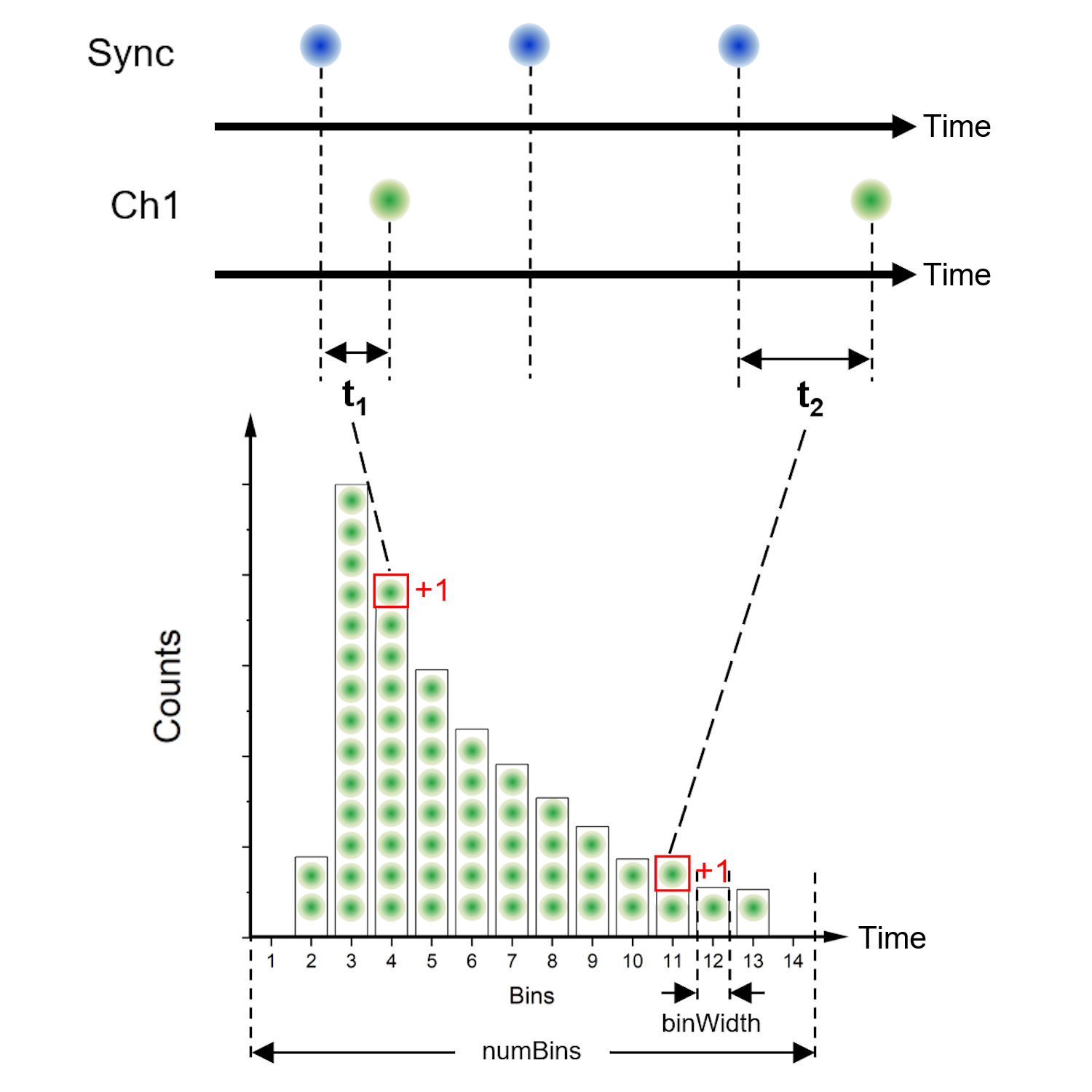
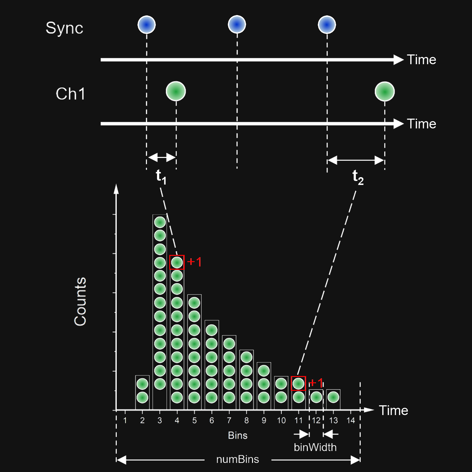
This figure shows the generation of a Histogram measurement.
Caution
To calculate the histogram in
MeasMode.T3it is necessary to store dTimes (time difference between the sync- and the channel events) in the returned bins array of the internal unfold data stream, because the sync events are removed. Therefore theManipulatorsmay work different than with absolute times stored in the unfold data stream. They may only be correct in between there sync periods. If you need the default behaviour you have to use theMeasMode.T2instead.- setRefChannel(channel=0)#
This function sets the reference channel used to calculate the time differences with respect to the other channels. The histograms are then created from these calculated data.
Note
Only meaningful in
MeasMode.T2.- Parameters:
channel (int (default: 0 sync channel)) – the reference channel (0 is sync channel)
- Return type:
None
Example
# creates a histogram in :obj:`.MeasMode.T2` with channel 1 as reference channel
sn = snAPI()
sn.getDevice()
sn.initDevice(MeasMode.T2)
sn.histogram.setRefChannel(1)
sn.histogram.measure(1000)
data, bins = sn.histogram.getData()
        ...
- setNumBins(numBins=10000)#
This function sets the number of bins used to calculate the time differences with respect to the other channels. The histograms are then created from these calculated data.
Note
Only meaningful in
MeasMode.T2.- Parameters:
numBins (int (default: 65536 bins))
- Return type:
None
Example
# creates a histogram in :obj:`.MeasMode.T2` with channel 1 as reference channel and 100000 bins
sn = snAPI()
sn.getDevice()
sn.initDevice(MeasMode.T2)
sn.histogram.setRefChannel(1)
sn.histogram.setNumBins(100000)
sn.histogram.measure(1000)
data, bins = sn.histogram.getData()
        ...
- setBinWidth(binWidth=None)#
This function sets the binWidth of the time differences for the histograms are to be build.
Note
Only meaningful in
MeasMode.T2.- Parameters:
binWidth (int (default: BaseResolution)) – the bin width in ps
- Return type:
None
Example
# creates a histogram T2 mode with bin width of 5ps
sn = snAPI()
sn.getDevice()
sn.initDevice(MeasMode.T2)
sn.histogram.setBinWidth(5)
sn.histogram.measure(1000)
data, bins = sn.histogram.getData()
        ...
- measure(acqTime=1000, waitFinished=True, savePTU=False)#
With this function a measurement and creation of a histogram us initiated, which ist stored into RAM and/or disc. If waitFinished is set True the call will be blocked until the measurement is completed. If waitFinished is set to False (default) you can get updates on the fly, and you can access the execution status with the
isFinished()function. If you wish to obtain updates on the fly the data can be accessed withgetData().Note
If you want to write the data to disc only, set the size to zero.
Warning
If the colleted data exceeds the buffer size a warning will be added to the log: ‘WRN UfStore buffer overrun - clearing!’ and the internal buffer will be cleared. This means that this part of data is lost! To prevent this, you should reduce the count rate.
- Parameters:
acqTime (int (default: 1000 ms)) –
0: means the measurement will run untilstopMeasure()acquisition time [ms]will be ignored if device is a FileDevicesize (int number of records (default: 128 million records = 1GB)) – memory size for the data array
waitFinished (bool (default: True)) – True: block execution until finished (will be False on acqTime = 0)
savePTU (bool (default: False)) – Save data to ptu file
- Returns:
True (operation successful)
False (operation failed)
Example
# calculates `Histogram` data for 1 sec in MeasMode.T2
sn = snAPI()
sn.getDevice()
sn.initDevice(MeasMode.T2)
sn.histogram.measure(1000)
data, bins = sn.histogram.getData()
- getData()#
This function returns the data of the histogram measurement.
- Parameters:
None
- Returns:
- histogram: 1DArray[int]
data array of counts
- bins: 1DArray[int]
data array of bins [ps]
- Return type:
tuple [1DArray, 1DArray]
Example
# reads `Histogram` data every second for 10 seconds :obj:`.MeasMode.T3`
sn = snAPI()
sn.getDevice()
sn.initDevice(MeasMode.T2)
sn.device.setInputDeadTime(-1,1000)
waitFinished = False
sn.device.setStopOverflow(1000000)
sn.histogram.setRefChannel(0)
sn.histogram.measure(100000, waitFinished, False)

while True:
    data, bins = sn.histogram.getData()
    ...

    if waitFinished or sn.histogram.isFinished():
        break
- stopMeasure()#
After a measurement is started it will normally be left running until the defined acquisition time has elapsed. However, sometimes it may be necessary to stop a measurement manually with this function.
- Parameters:
None
- Return type:
None
- clearMeasure()#
Some measurements calculate their results on large sets of historical data. When conditions have changed, the old data may need to be deleted to get an unobstructed view of the new data. This function deletes the internal data without having to restart the measurement.
- Parameters:
None
- Return type:
None
- isFinished()#
This function reports whether the measurement is finished.
Warning
If the measurement is finished, there might be some data available, which was not retrieved yet. It may be necessary to call
getData()orgetBlock()once again after isFinished returns True. Check out the example of a possible implementation below.- Parameters:
None
- Returns:
True (the measurement is finished)
False (the measurement is running)
Example
# runs a while loop until the measurement is finished
    while sn.histogram.isFinished():
    data = sn.histogram.getData()
        ...

# break a while loop if the measurement is finished and reads the last data
    while True:
    finished = sn.histogram.isFinished()
    data = sn.histogram.getData()
        ...

    if finished:
        break
- class snAPI.Main.TimeTrace#
Bases:
objectThis measurement class provides you with time trace data. This can be used for real-time calibration of and optimization ae measurement setup.
Note
Only meaningful in
MeasMode.T2andMeasMode.T3.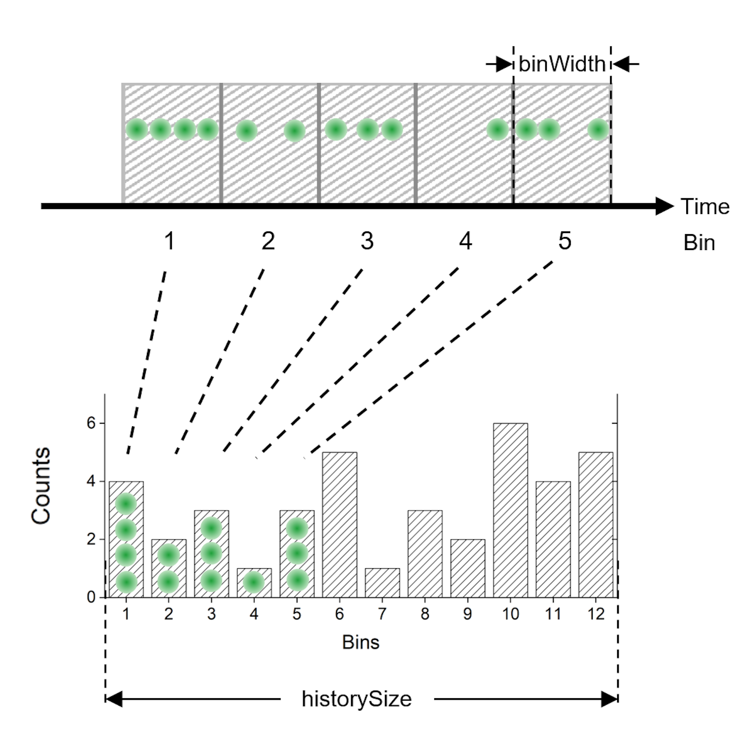
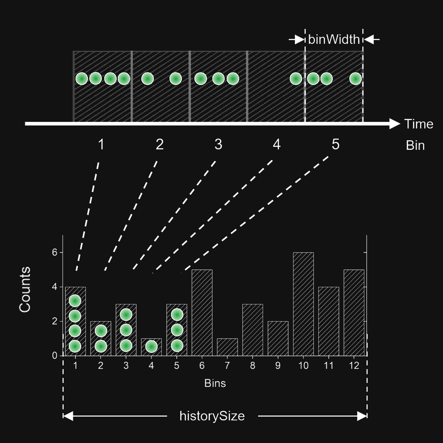
This figure shows the principle of the TimeTrace measurement.
- setNumBins(numBins=10000)#
This function sets the number of bins into which the counts are sorted.
Note
The bin width can calculated as \(binWidth = historySize / numBins\).
- Parameters:
numBins (int (default: 10000)) – number of bins
- Return type:
None
Example
# sets thew number of bins to 10000
sn.timeTrace.setNumBins(10000)
- setHistorySize(historySize=1)#
This function sets the length or duration of the recorded data in the time domain in which the counts are collected.
Warning
It is possible to set the history size to nanoseconds to see the individual photons. However, because the data is processed in real time this may not be sustainable for live measurements at high count rates. If the data is read from a file it will work at any rate, but processing the file may take longer than it took to record it.
Note
The bin width can calculated as \(binWidth = historySize / numBins\).
- Parameters:
historySize (float [s] (default: 1s)) – length or duration of the recorded data in the time domain
- Return type:
None
Example
# sets a history size of 10s
sn.timeTrace.setHistorySize(10)
- measure(acqTime=1000, waitFinished=False, savePTU=False)#
With this function a simple TimeTrace measurement into RAM and/or disc is provided. When waitFinished is set True the call will block until the measurement is completed. However, in most cases you probably want to avoid blocking in order to retrieve and display the data in real time. the data can be accessed with
getData().- Parameters:
acqTime (int (default: 1000 ms)) –
0: means the measurement will run untilstopMeasure()acquisition time [ms]will be ignored if device is a FileDevicewaitFinished (bool (default: False)) – True: block execution until finished (will be False on acqTime = 0)
savePTU (bool (default: False)) – Save data to ptu file
- Returns:
True (operation successful)
False (operation failed)
Example
# gets real time data with a history size of 10s
...
sn.getDevice()
sn.getFileDevice(r"E:\Data\PicoQuant\HH400-PMT-cw-1MHz.ptu")
sn.initDevice(MeasMode.T2)
sn.timeTrace.setNumBins(10000)
sn.timeTrace.setHistorySize(10)
- getData(normalized=True)#
This function returns the data of the time trace measurement. The data is optimized for display in a chart and therefore held in a FIFO buffer.
- Parameters:
normalized (bool (default: True)) – The counts will be normalized to its bin width, otherwise you get the absolute number of count per bin
- Returns:
- data: 1DArray[int]
data array of counts normalized to counts per second \(countsPerSecond = countsPerBin * historySize / numBins\)
- times: 1DArray[int]
data array of the start times of the bins from the beginning of the measurement [s]
- Return type:
tuple [1DArray, 1DArray]
Example
# plots a time trace from a file
...
sn = snAPI()
sn.getDevice()
sn.getFileDevice(r"E:\Data\PicoQuant\CW_Shelved.ptu")
sn.timeTrace.setNumBins(10000)
sn.timeTrace.setHistorySize(255)
sn.timeTrace.measure()
counts, times = sn.timeTrace.getData()
plt.clf()
plt.plot(times, counts[0], linewidth=2.0, label='sync')
plt.plot(times, counts[1], linewidth=2.0, label='chan1')
plt.plot(times, counts[2], linewidth=2.0, label='chan2')
plt.plot(times, counts[3], linewidth=2.0, label='chan3')
plt.xlabel('Time [s]')
plt.ylabel('Counts[Cts/s]')
plt.legend()
plt.title("TimeTrace")
plt.pause(0.01)
plt.show(block=True)
- isFinished()#
This function reports whether the measurement is finished.
Warning
If the measurement is finished, there might be some data available, which was not retrieved yet. It may be necessary to call
getData()orgetBlock()once again after isFinished returns True. Check out the example of a possible implementation below.- Parameters:
None
- Returns:
True (the measurement is finished)
False (the measurement is running)
Example
# runs a while loop until the measurement is finished
    while !sn.timetrace.isFinished():
    data = sn.timetrace.getData()
        ...

# break a while loop if the measurement is finished and reads the last data
    while True:
    finished = sn.timetrace.isFinished()
    counts, times = sn.timetrace.getData()
        ...

    if finished:
        break
- stopMeasure()#
After a measurement is started it will normally be left running until the defined acquisition time has elapsed. However, sometimes it may be necessary to stop a measurement manually with this function.
- Parameters:
None
- Return type:
None
- clearMeasure()#
Some measurements calculate their results on large sets of historical data. When conditions have changed, the old data may need to be deleted to get a an unobstructed view of the new data. This function deletes the internal data without having to restart the measurement.
- Parameters:
None
- Return type:
None
- class snAPI.Main.Correlation#
Bases:
objectThis is the correlation measurement class with which it is possible to perform FCS (Fluorescence Correlation Spectroscopy) or g(2) correlations. The g(2) correlation is calculated with bins of the same width while the FCS correlation with the multi-tau algorithm uses pseudo-logarithmically increasing bin widths.
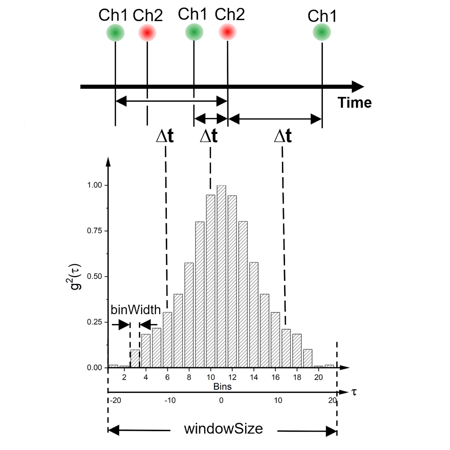
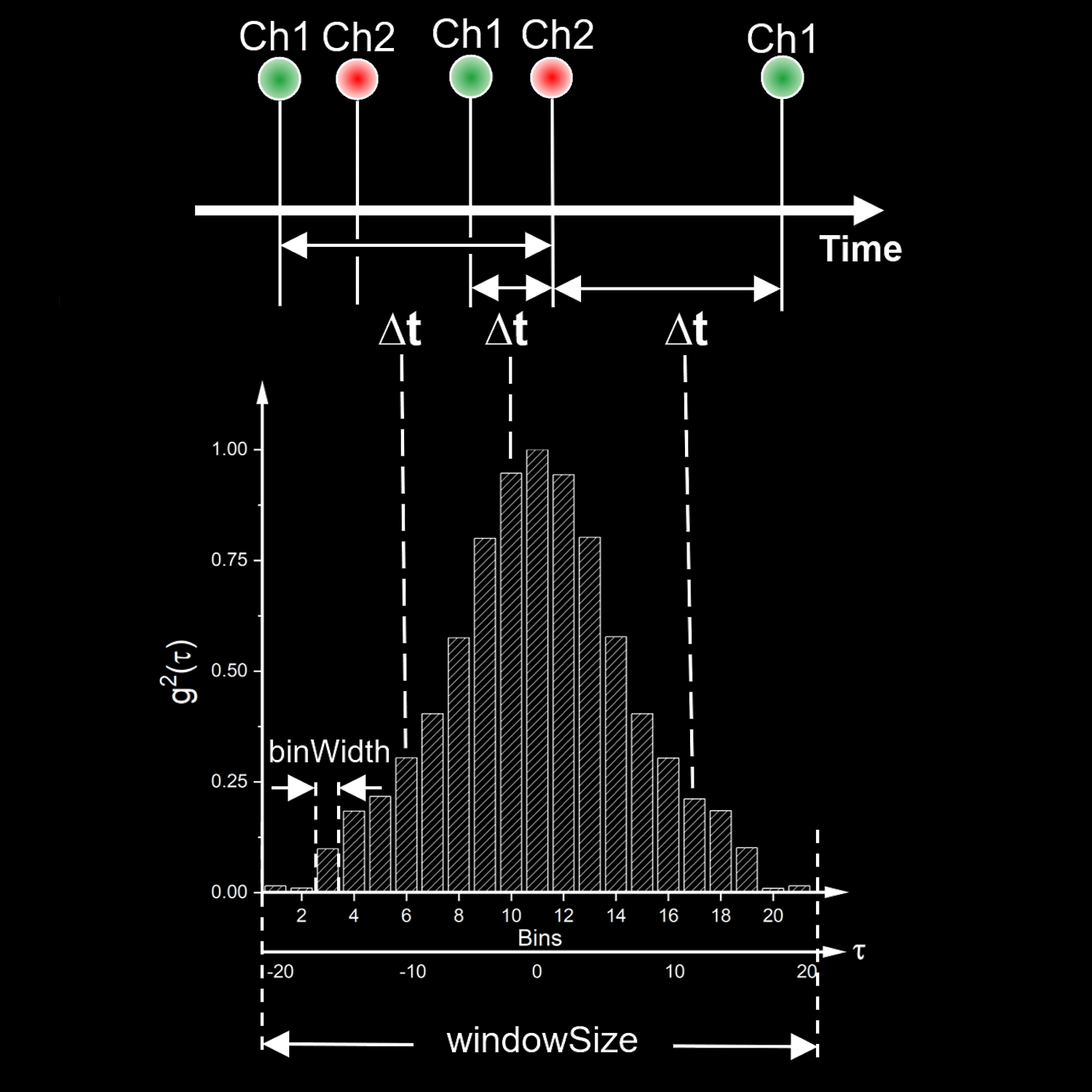
This figure shows the principle of the Correlation measurement.
- setG2Parameters(startChannel, stopChannel, windowSize, binWidth=None, normalization=True)#
This function sets the the parameters for the g(2) correlation. If the startChannel is the same as the stopChannel an autocorrelation is performed and if the channels are different a cross calculation is done instead.
Note
The g(2) correlation is normalized with the following factor:
(1)#\[\frac{\Delta t}{binWidth \cdot N_1 \cdot N_2}\]Here the \(\Delta t\) term represents the total time span of the correlation, and \(N_1\) and \(N_2\) represent the total number of events in the two detection channels during this time span.
- Parameters:
startChannel (int (0 is sync channel)) – start channel
stopChannel (int (0 is sync channel)) – click channel
windowSize (int [ps]) – size of the correlation window
binWidth (int [ps]) – width of bins (Default: None - T2: BaseResolution, T3: Resolution)
normalization (bool (default: True)) – allows to disable normalization (for quantum experiments to count coincidences)
- Return type:
None
Example
# sets the window size to 5000ps with a bin width of 5ps (that means 1000 bins will be calculated)
sn.correlation.setG2Parameters(1, 2 , 5000, 5)
- setFCSParameters(startChannel, stopChannel, startTime=1000000.0, stopTime=1000000000000.0, numBins=30)#
This function sets the the parameters for the FCS correlation. If the startChannel is the same as the stopChannel an autocorrelation is calculated and if the channels are different a cross calculation is calculated.
- Parameters:
startChannel (int (0 is sync channel)) – start channel
stopChannel (int (0 is sync channel)) – click channel
startTime (float [ps]) – minimum lag time of the correlation window
stopTime (float [ps]) – maximum lag time of the correlation window
NumBins (int [ps]) – number of bins
numBins (int | None)
- Return type:
None
Example
# sets the correlation window to start by 1ms and stop by 1s with 30 bins
sn.correlation.setG2Parameters(1, 2 , 1e6, 1e12, 30)
- setFFCSParameters(startChannel, stopChannel, startTime=1000000.0, stopTime=1000000000000.0, numBins=30)#
This function sets the the parameters for the Fast-FCS correlation. This new algorithm is optimized for longer windowSize`s. If you have a short `windowSize or a low count rate it may better to use the classical
setFFCSParameters(). If the startChannel is the same as the stopChannel an autocorrelation is calculated and if the channels are different a cross calculation is calculated.- Parameters:
startChannel (int (0 is sync channel)) – start channel
stopChannel (int (0 is sync channel)) – click channel
startTime (float [ps]) – minimum lag time of the correlation window
stopTime (float [ps]) – maximum lag time of the correlation window
NumBins (int [ps]) – number of bins
numBins (int | None)
- Return type:
None
Example
# sets the correlation window to start by 1ms and stop by 1s with 30 bins
sn.correlation.setFFCSParameters(1, 2 , 1e6, 1e12, 30)
- measure(acqTime=1000, waitFinished=False, savePTU=False)#
With this function a simple Correlation measurement is initiated. The results are stored into RAM and/or disc. If waitFinished is set True the call will be blocked until the measurement is completed. If waitFinished is set False (default) you can get updates on the fly, and you can access the execution status with the
isFinished()function. The data can be accessed withgetData().- Parameters:
acqTime (int (default: 1000 ms)) –
0: means the measurement will run untilstopMeasure()acquisition time [ms]will be ignored if device is a FileDevicewaitFinished (bool (default: False)) – True: block execution until finished (will be False on acqTime = 0)
savePTU (bool (default: False)) – Save data to ptu file
- Returns:
True (operation successful)
False (operation failed)
Example
# calculates the g2 correlation of ptu file
sn = snAPI()
sn.getDeviceIDs()
sn.getDevice()
sn.getFileDevice(r"E:\Data\PicoQuant\CW_Shelved.ptu")
sn.correlation.setG2Parameters(1, 2, 1000, 200)
sn.correlation.measure()

while True:
    finished = sn.correlation.isFinished()
    data, bins = sn.correlation.getData()

if sn.correlation.isFinished():
    break
- getG2Data()#
This function returns the data of the g(2) correlation measurement.
- Parameters:
None
- Returns:
- data: 1DArray[int]
data array of the normalized g(2) measurement (1)
- bins: 1DArray[int]
data array of the start times of bins from the beginning of the measurement [s]
- Return type:
tuple [1DArray, 1DArray]
Example
# correlates the data from a file and plots the result
...
sn = snAPI()
sn.getDevice()
sn.getFileDevice(r"E:\Data\PicoQuant\CW_Shelved.ptu")
sn.correlation.setG2Parameters(1, 2, 1000, 200)
sn.correlation.measure()

while True:
    data, bins = sn.correlation.getG2data()
    if len(data) > 0:
        plt.clf()
        plt.plot(bins, data, linewidth=2.0, label='g(2)')
        plt.xlabel('Time [s]')
        plt.ylabel('g(2)')
        plt.legend()
        plt.title("g(2)")
        plt.pause(0.01)

    if sn.correlation.isFinished():
            break

plt.show(block=True)
- getFCSData()#
This function returns the data of the FCS correlation measurement.
- Parameters:
None
- Returns:
- data: 2DArray[int]
data array of the FCS measurement. (A->A | A->B | B->B)
- bins: 1DArray[int]
data array of the times of the bins
- Return type:
tuple [2DArray, 1DArray]
Example
# FCS of the data from a file and plotting the result
...
sn = snAPI()
sn.getDeviceIDs()
sn.getDevice()
sn.getFileDevice(r"E:\Data\PicoQuant\CW_Shelved.ptu")
sn.correlation.setFCSparameters(1, 2, 1e5, 1e12, 100)
sn.correlation.measure()

while True:
    finished = sn.correlation.isFinished()
    data, bins = sn.correlation.getFCSdata()
    if len(data) > 0:
        plt.clf()
        plt.plot(bins, data[0], linewidth=2.0, label='AA')
        plt.plot(bins, data[1], linewidth=2.0, label='AB')
        plt.plot(bins, data[2], linewidth=2.0, label='BB')
        plt.xlabel('Time [s]')
        plt.xscale('log')
        plt.ylabel('FCS')
        plt.legend()
        plt.title("FCS")
        plt.pause(0.01)

    if finished:
        break

plt.show(block=True)
- stopMeasure()#
After a measurement is started it will normally be left running until the defined acquisition time has elapsed. However, sometimes it may be necessary to stop a measurement manually with this function.
- Parameters:
None
- Return type:
None
- clearMeasure()#
Some measurements calculate their results on large sets of historical data. When conditions have changed, the old data may need to be deleted to get a fresh view of the new data. This function deletes the internal data without having to restart the measurement.
- Parameters:
None
- Return type:
None
- isFinished()#
This function reports whether the measurement is finished.
Warning
If the measurement is finished, there might be some data available, which was not retrieved yet. It may be necessary to call
getData()orgetBlock()once again after isFinished returns True. Check out the example of a possible implementation below.- Parameters:
None
- Returns:
True (the measurement is finished)
False (the measurement is running)
Example
# runs a while loop until the measurement is finished
    while sn.correlation.isFinished():
    data = sn.correlation.getData()
        ...

# break a while loop if the measurement is finished and reads the last data
    while True:
    finished = sn.correlation.isFinished()
    data = sn.correlation.getData()
        ...

    if finished:
        break
- class snAPI.Main.Manipulators#
Bases:
objectThis is the manipulators class. It can be used to modify the unfold data stream in snAPI. It it is possible to modify existing channel records and/or create or delete new ones which are then added to the data stream.
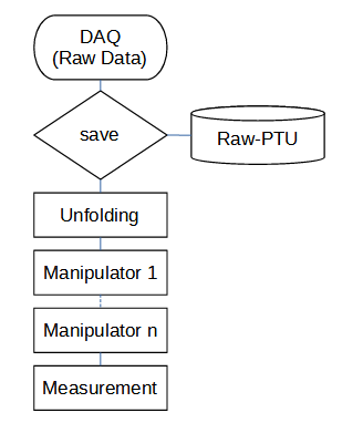
This figure shows the flow chart of the integration of the Manipulators.
- config = []#
Stores a list of the defined manipulators and can manually read with
getConfig()Note
The Manipulator.config can not be written to. It is only for checking the current state. To change the configuration, you have to call the specific functions directly.
Example
# example of a manipulator config

{
"ManisCfg": [
    {
    "Index": 0,
    "Type": "Herald",
    "Channels": [
        {
            "Channel": 5
        },
        {
            "Channel": 6
        }
        ]
    },
    {
        "Index": 1,
        "Type": "Coincidence",
        "Channels": [
        {
            "Channel": 7
        }
        ]
    },
    {
        "Index": 2,
        "Type": "Delay",
        "Channels": [
        {
            "Channel": 8
        }
        ]
    },
    {
        "Index": 3,
        "Type": "Coincidence",
        "Channels": [
        {
            "Channel": 9
        }
        ]
    }
]
}
- getConfig()#
This command reads the manipulator configuration stored by th API and returns it to
config.Note
Normally you do not have to to call this function in order to refresh the manipulator.config. It should always be up to date. However, under certain circumstances it might be desired to update the manipulator.config manually.
- Parameters:
None
- Returns:
True (operation successful)
False (operation failed)
Example
# reads the manipulator config from the API

sn.manipulator.getConfig()
- clearAll()#
This clears all manipulators.
Warning
It is not allowed to clear the manipulators while acquisition is running!
- coincidence(chans, windowTime=1000, mode=CoincidenceMode.CountAll, time=CoincidenceTime.Last, keepChannels=True)#
This creates a coincidence manipulator. You have to define which channels should be part of the coincidence and its window size.
Note
If only the coincidence channel is needed for further investigations set keepChannels to False. This will reduce the data stream and therefore the processor load and memory consumption.
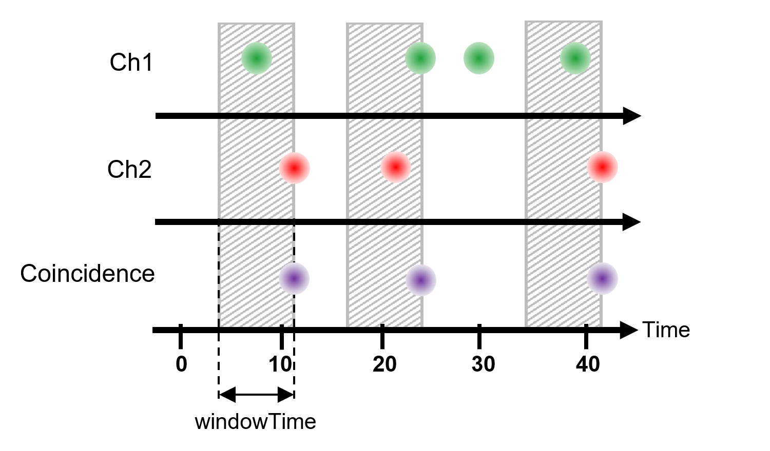
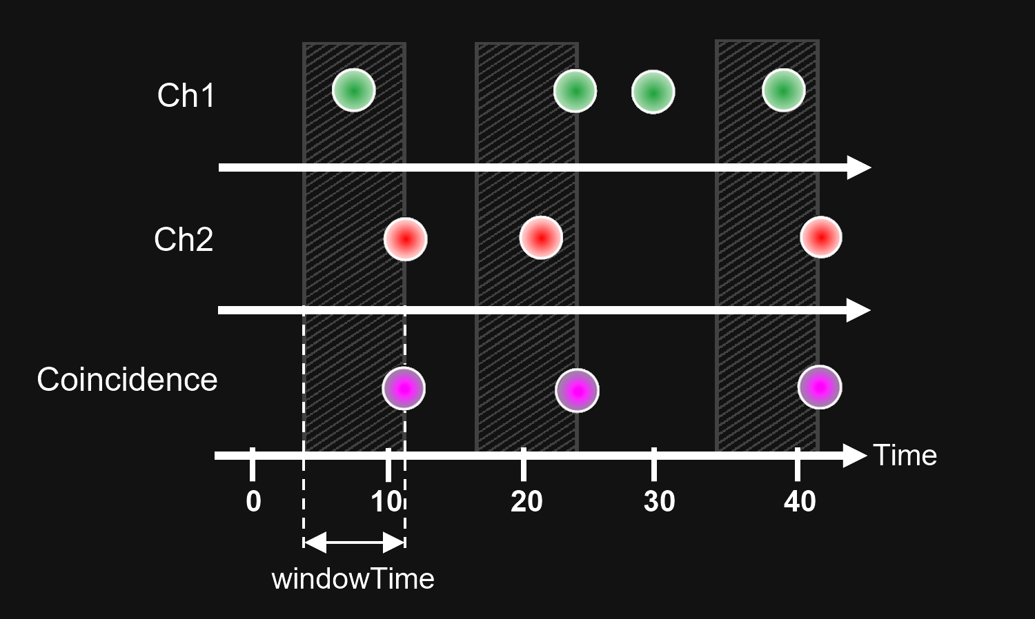
This figure shows the principle of the Coincidence.
- Parameters:
chans (List[int]) – channel indices that build a coincidence
windowTime (float) – window size [ps]
mode (CoincidenceMode (default: CoincidenceMode.CountAll)) – coincidence counting mode
keepChannels (bool (default: True)) –
True: the coincidence channel is be integrated in the data stream as an additional channelFalse: only the coincidence channel is in the data streamtime (CoincidenceTime | None)
- Returns:
the channel index of the coincidence
- Return type:
int
Example
# plots a timetrace of channel 1 and 2 and their coincidence within a window time of 1ns

sn = snAPI()
sn.getFileDevice(r"C:\Data\PicoQuant\default_1.ptu")

sn.timeTrace.setNumBins(10000)
sn.timeTrace.setHistorySize(10)

ci = sn.manipulators.coincidence([1, 2], 1000)

sn.timeTrace.measure(10000, False, False)

while True:
    finished = sn.timeTrace.isFinished()
    counts, times = sn.timeTrace.getData()
    plt.clf()
    plt.plot(times, counts[1], linewidth=2.0, label='chan1')
    plt.plot(times, counts[2], linewidth=2.0, label='chan2')
    plt.plot(times, counts[ci], linewidth=2.0, label='coincidence 1&2-1ns')

    plt.xlabel('Time [s]')
    plt.ylabel('Counts[Cts/s]')
    plt.legend()
    plt.title("TimeTrace")
    plt.pause(0.1)

    if finished:
        break

plt.show(block=True)
- merge(chans, keepChannels=True)#
This manipulator combines the data steam of the specified channels. You only have to define which channels should be merged.
Note
If only the merged channel is needed for further investigations set keepChannels to False. This will reduce the data stream and therefore the processor load and memory consumption.
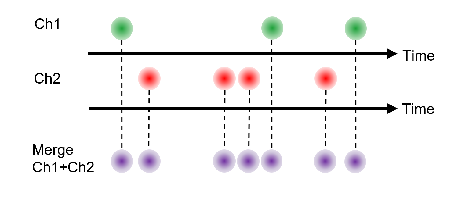
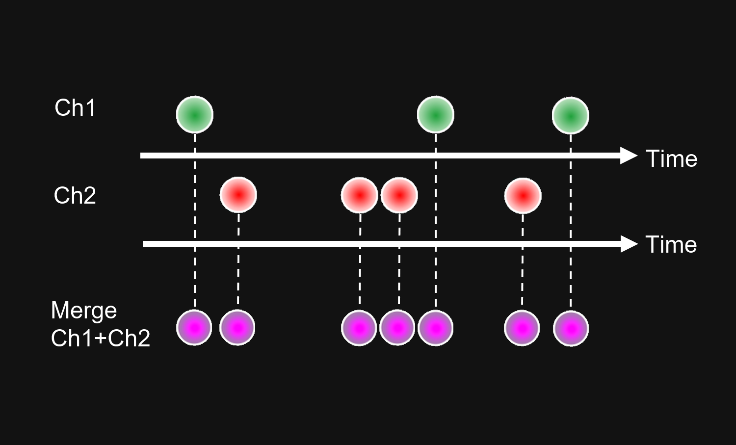
This figure shows the Merge operator principle.
- Parameters:
chans (List[int]) – channel indices to be merged
keepChannels (bool (default: True)) –
True: the merged channel is be integrated in the data stream as additional channelFalse: only the merged channel is in the data stream
- Returns:
the merged channel index
- Return type:
int
Example
# the example looks like a coincidence example except the configuration of the manipulator
# this would merge the channels 1 and 2

cm = merge([1,2])
- delay(channel, delayTime, keepSourceChannel=True)#
This manipulator, gives you the ability to add a delay to the specified channels. Its generally better to use
setInputChannelOffset()because it does the same but on a hardware level and therefore it doesn’t uses any resources of the PC. But if you handle data of a ptu file this is the only.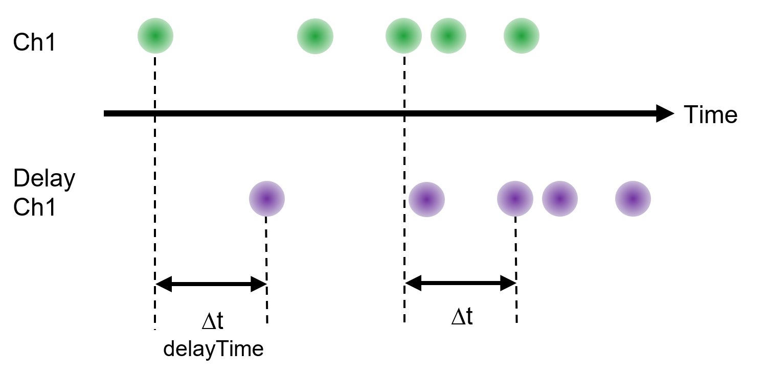
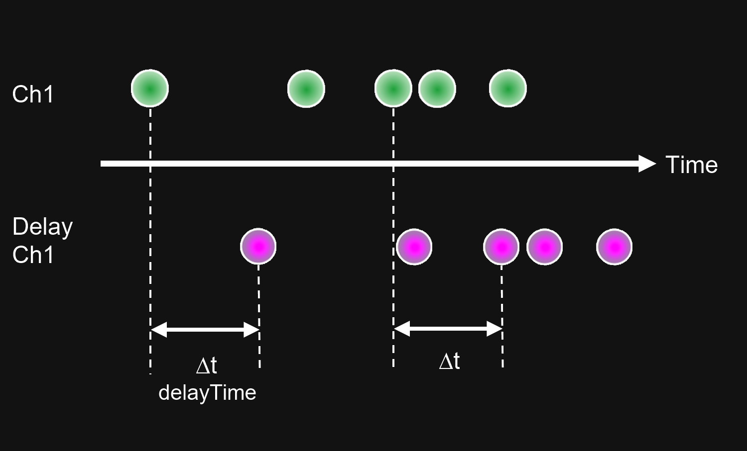
This figure shows the principle of the Delay operator.
Note
If you don’t need the original channel anymore set keepSourceChannel to False. This will reduce the data stream and therefore the processor load and memory consumption.
- Parameters:
channel (int) – index of the channels, for which a coincidence will be calculated
delayTime (int) – window size [ps]
keepSourceChannel (bool (default: True)) –
True: the delayed channel is being integrated in the data stream as an additional channelFalse: the source channel will be delayed
- Returns:
the index of the channel to be delayed
- Return type:
int
Example
# creates a delay of channel 1 with 1ms and stores it in cd

sn = snAPI()
sn.getFileDevice(r"D:\Data\PicoQuant\CW_Shelved.ptu")
sn.timeTrace.setNumBins(10000)
sn.timeTrace.setHistorySize(10)

sn.manipulators.delay(1, 1000000000)

sn.timeTrace.measure(10000, False, False)

while True:
    finished = sn.timeTrace.isFinished()
    counts, times = sn.timeTrace.getData()
    plt.clf()
    plt.plot(times, counts[1], linewidth=2.0, label='chan1')
    plt.plot(times, counts[cd], linewidth=2.0, label='delay 1ms')

    plt.xlabel('Time [s]')
    plt.ylabel('Counts[Cts/s]')
    plt.legend()
    plt.title("TimeTrace")
    plt.pause(0.1)

    if finished:
        break

plt.show(block=True)
- subStream(startTime=0, stopTime=360000)#
The Sub-Stream Manipulator filters the datastream by a defined start and stop time. Only events whose timetags fall within this range will pass through.
This is useful when you want to analyze only a specific segment of a measurement or exclude irrelevant data.
Note
The filter applies directly to all channels!
- Parameters:
startTime ([s] double) –
The lower boundary in seconds of the interval.Events with timestamps equal to or greater than this are passed through.stopTime ([s] double) –
The upper boundary of the interval.Events with timestamps greater than this are discarded.
- Return type:
None
Example
# creates a delay of channel 1 with 1ms and stores it in cd

sn = snAPI()
sn.getFileDevice(r"D:\Data\PicoQuant\CW_Shelved.ptu")
sn.timeTrace.setNumBins(10000)
sn.timeTrace.setHistorySize(10)

subStream(70) # ignore the first 70 seconds oof the measurement file

sn.timeTrace.measure(10000, False, False)

while True:
    finished = sn.timeTrace.isFinished()
    counts, times = sn.timeTrace.getData()
    plt.clf()
    plt.plot(times, counts[1], linewidth=2.0, label='chan1')

    plt.xlabel('Time [s]')
    plt.ylabel('Counts[Cts/s]')
    plt.legend()
    plt.title("TimeTrace")
    plt.pause(0.1)

    if finished:
        break

plt.show(block=True)
- herald(herald, gateChans, delayTime=0, gateTime=1000, inverted=False, keepChannels=True)#
This manipulator performs as heralded gate filter. You have to define from which channel the herald events will be taken and which channels will be filtered. Therefore it is been necessary to set the delay time and the gate time of the following gate accordingly.
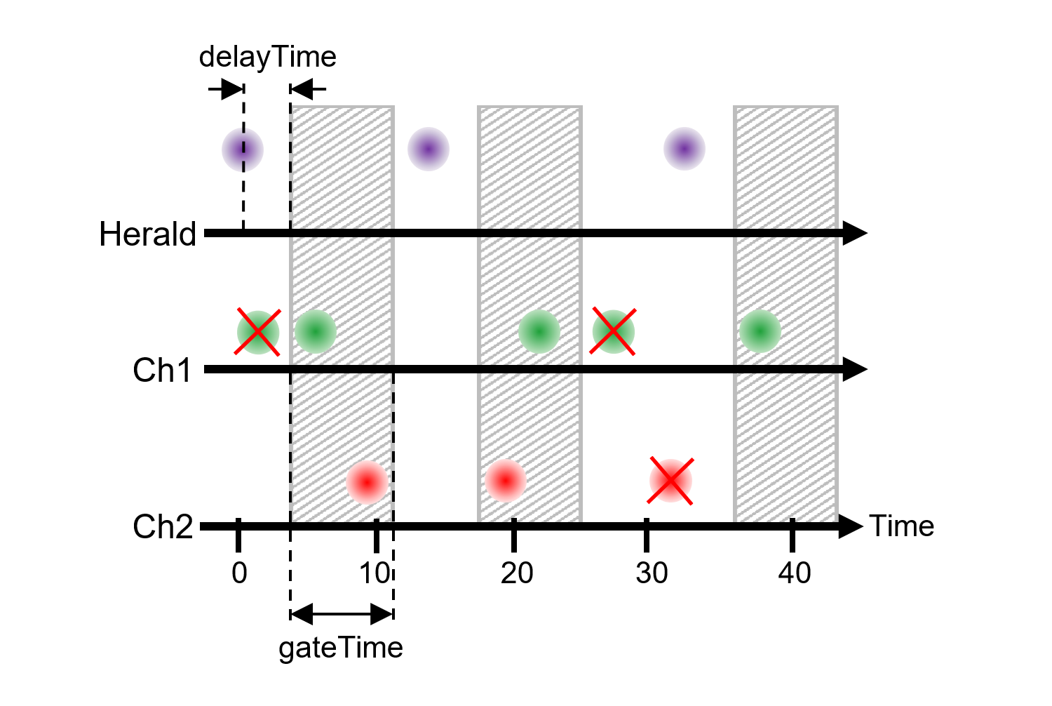
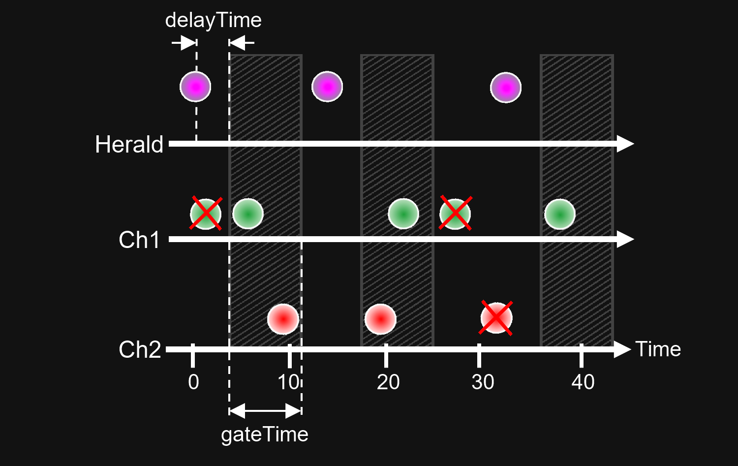
This figure shows the principle of the Herald operator.
Note
If only the gated channels are needed for further investigations set keepChannels to False. This will reduce the data stream size and therefore the processor load and memory consumption.
Caution
To calculate the histogram in
MeasMode.T3it is necessary to store dTimes (time difference between the sync- and the channel events) in the internal unfold data stream, because the sync events are removed. Therefore the herald manipulator only works in between to sync pulses. If you need the default behaviour you have to use theMeasMode.T2instead.- Parameters:
herald (int) – the channel that contains the herald events
gateChans (List[int]) – channel numbers that should be gated
delayTime ((default: 0ps)) – time between the herald event and the start of the gate
gateTime (int (default: 1ns)) – size of the gate [ps]
inverted (bool (default: False)) –
True: inverted logic (The events in the herald window will be removed)False: only the events inside the defined window will pass this filterkeepChannels (bool (default: True)) –
True: the gate channels are to be integrated in the data stream as additional channelsFalse: the gate channels are directly filtered
- Returns:
the channel indices of the gated channels
- Return type:
int
Example
# sets a herald on sync channel that cuts of a window from 66ns to 76ns from channel 2

sn = snAPI()
sn.getDevice()
sn.initDevice(MeasMode.T2)
waitFinished = False
hChans = sn.manipulators.herald(0, [2], 66000, 10000, True)
sn.histogram.setRefChannel(0)
sn.histogram.setBinWidth(5)
sn.histogram.measure(10000, False)

while True:
    finished = sn.histogram.isFinished()
    data, bins = sn.histogram.getData()

    plt.clf()
    plt.plot(bins, data[2], linewidth=2.0, label='chan2')
    plt.plot(bins, data[hChans[0]], linewidth=2.0, label='heralded')
    plt.xlabel('Time [ps]')
    plt.xlim(67000, 73000) #set the scale range of the time scale to the region of interest
    plt.ylabel('Counts')
    plt.yscale('log')
    plt.legend()
    plt.title("Histogram")

    if waitFinished or finished:
        break

plt.show(block=True)
- countrate(windowTime=100000000000.0)#
This manipulator, gives you the ability to measure the count rate inside the unfold data stream. You can use multiple times, maybe before and after the herald manipulator to measure the filter rate. The
count ratefunction adds this manipulator and thegetCountratesreturns the measured count rates.- Parameters:
windowTime (float (default: 100ms)) – window size [ps]
- Returns:
the index of the manipulator that measures the count rate
- Return type:
int
Example
windowSize = 300 #ps
# move the histograms of the both channels to the same time after the sync to filter both at once
sn.device.setInputChannelOffset(0,4500)

# measure the   before the herald filter
CrInIdx = sn.manipulators.countrate()

# define a gate window after the herald channel 0 (sync) for the detector channels 1 and 2,
# starting at 52000 ps after the herald signal , with a gate length of windowSize (300 ps)
heraldChans = sn.manipulators.herald(0, [1,2], 52000, windowSize, keepChannels=False )

# measure the count rate after the herald filter
CrOutIdx = sn.manipulators.countrate()

# initiate the g2 correlation with the time-gated channels
sn.correlation.setG2Parameters(heraldChans[0], heraldChans[1], windowSize, 1)
sn.correlation.measure(100000,savePTU=False)

while True:
    finished = sn.correlation.isFinished()
    data, bins = sn.correlation.getG2Data()

    CRin = sn.manipulators.GetCountrates(CrInIdx)
    CRout = sn.manipulators.GetCountrates(CrOutIdx)

    # print the count rates
    sn.logPrint(f"CR in: {CRin[1]}, {CRin[2]} - out: {CRout[heraldChans[0]]}, {CRout[heraldChans[1]]}")

    time.sleep(.3)

    plt.clf()
    plt.plot(bins, data, linewidth=2.0, label='g(2)')
- getCountrates(manipulatorIndex)#
This function is part of the
countratemaipulator. It gives the number of counts that where count in the defined windowTime.- Parameters:
manipulatorIndex (int) – index of count rate manipulator
- Returns:
the index of the manipulator that measures the countrate
- Return type:
int
Example
# gets the count rates of manipulator 0

CRs = sn.manipulators.GetCountrates(0)

